One of the main advantages when you replace an LC-controlled VFO by a DDS-System is, aside from frequency stability, the possibility to control your VFO(s) by software. When designing my handheld QRP-rig I intenionally left the 2 ports for RS232-communication at the ATMega328 unused.

I always had in mind that I might one day setup a computer control so that the radio can be controlled by a PC. This is handy when you use the rig as a station transceiver in your home shack.
OK, let’s go to the whole story. First the hardware.
This is an easy chapter: You just have to connect the TxD and RxD pins of the microcontroller to a level changer like the well-known MAX232 chip by Maxim. This one converts the 0..5 volts level of the Atmega328 to +/- 12V of a PC’s RS232 interface. Browse the web for applications, you will find a lot. This is my one:

Power supply of the interface is powered by the RS232 connector. No external supply is needed. Instead of line 7 (RTS) you can also use line 4 (DTR). That’s the hardware that is required.
Software consists of two parts. First we want to look at the program modules realized in the QRP-radio.
Programming the ATmega328 for communication with a PC
All ATmegas have got functionality for universal asynchronous receiver transmitter (UART, sometimes called USART if synchronous communication functions are also implemented). This device is capable of working a large variety of baud rates for universal serial communication.
The INIT-Function
UART has to be initialized for transmitting, receiving, for appropriate comm parameters etc. The respective function looks like this and has to be called before the first data exchange can take place:
void uart_init(int uartval)
{
    UBRR0H = 0;
    UBRR0L = uartval; //Set baud rate by this value (25 stands for 19200!)

    // Activate TX, RX and RX interrupt
    UCSR0B |= (1<<TXEN0) | (1<<RXEN0) | (1<<RXCIE0);

    // set comm parameters
    // 8 databit, 1 stopbit, no parity
    UCSR0C |= (1<<UCSZ01) | (1<<UCSZ00);

    rx_buf_cnt = 0;
}
The parameter uartval must be calculated by a given formula and sets the baud rate depending on clock speed used by the MUC. Here is an overview for all baud rates and lots of clock speeds. For 8 MHz clock speed and 19200 baud I use the value of 25.
//Init UART
uart_init(25); //19200 Baud
Note that the output pin TxD does not have to be configured as an output. This is automatically done when you use this pin for communication. Best practise is to call it in main() function before entering the infinite loop.
Next we want to see two subroutines that deal with transmitting signals. First one is just designed to send a single character. The second routine uses this one to transmit complete strings.
void uart_putc(char tx_char)
{
    while(!(UCSR0A & (1<<UDRE0)));

    UDR0 = tx_char;
}

void uart_send_string(char *s)
{

    while(*s != 0)
    {
        uart_putc(*(s++));
        _delay_ms(5);
    }
    uart_putc(13);
    uart_putc(10);
}
Making the UART receive
UART of ATmega328 has one register that stores any received value: The UDR0-register. This one can be read by polling the register regularly or by entering an interrupt (signal) routine that is only executed when a signal is received. The last choice is the way I prefer. If you want to do this, be sure that global interrupt flag is enabled by stating
sei();
at the beginning of your main() function!
Here ist the routine that reads the UDR0-register when a character is received. Two global variables are declared first:
char rx_buf[32] ;
rx_buf_cnt;
The first variable stores the received byte(s), the second one is a counter that is increased each time a character is received.
SIGNAL(USART_RX_vect)
{
    unsigned char rx_char = UDR0;

    cli();

    if((rx_char == 10) || (rx_char == 13) || (rx_buf_cnt > RX_BUF_SIZE))
    {
        exec_command(rx_buf);
        clear_rx_buf();
        rx_buf_cnt = 0;
    }
    else
    {
        rx_buf[rx_buf_cnt++] = rx_char;
    }

    sei();
}
If there is a combination of CR and LF detected the received data will be checked what the user wants the software to do. Afterwards the receive buffer will be cleared. Two other functions are neccessary for this:
exec_command() uses the received characters to execute specific commands in the radio trasmitted by the user at the PC. clear_rx_buf() sets rx_buf[] variable to zero again and initializes the counter with 0.
// Set rx_buf to zero
void clear_rx_buf()
{
    int t1;

    for(t1 = 0; t1 < RX_BUF_SIZE; t1++)
    rx_buf[t1] = 0;
    rx_buf_cnt = 0;
}
//Execute the command that has been received by UART
//There are 2 basic set of commands
//
//a) (S)ET: Set a VFO or a frequency for example
//   Syntax: (S)ET(V)FO(X) = "SVX"
//           (S)ET(Q)RG(14234567)  = SQ14234567
//
//b) GET:
//   (G)ET(F)requency: Get current VFO-Frequency
//
void exec_command(char *com_str)
{
    unsigned long qrg = 0, fdec = 10000000;
    int t1;
    char *numstr = "            ";

    for(t1 = 0; t1 < 12; t1++)
    {
        *(numstr + t1) = 0;
    }


    if(com_str[0] == 'S') //Set-command detected
    {
        switch(com_str[1]) //Search sub command
        {
            //SETVFO-command detected
            case('V'): if((com_str[2] >= 'A') && (com_str[2] <= 'M'))
            {
                vfo_cnt = com_str[2] -65;
                set_frequency(vfo[vfo_cnt],interfreq, AD9835UPDATE);
                show_vfo(vfo_cnt) ;
            }
            break;

            //SETQRG-command detected
            case('Q'):  for(t1 = 2; t1 < 9; t1++)
            {
                qrg += (com_str[t1] - 48) * fdec;
                fdec /= 10;
            }
            vfo[vfo_cnt] = qrg;
            set_frequency(qrg,interfreq, AD9835UPDATE);
            break;

        }
    }

    if(com_str[0] == 'G') //GET-command detected
    {
        switch(com_str[1]) //Search sub command
        {
            //GET frequency-command detected
            case('F'):  lng2str(vfo[vfo_cnt], numstr);
            uart_send_string(numstr);
            break;
        }
    }

}
How this function works:
Commands are combinations of two letters and maybe a parameter. If the first letter is an “S” a SET-command is performed. Something in the transceiver will be changed. If there is a “G”, a reading operation has been received and the requested data will be sent to the PC.
Examples: “SQ14256000” stands for “Set QRG 14.256 MHz”. “SVA” switches to internal VFOA of the radio (“Set VFO A“). “GF” is a “Get Frequency”-command and sends the frequency of the current VFO to the PC as a string. Therefore the function lng2str() has been created. This function manipulates a char-pointer given as a parameter to convert a numeric value to a *char pointer. Notice that therefore there is no return value. String data will be written to the given pointer adress.
//Convert a number to a pointer
void lng2str(long num, char *s)
{

    long t1, t2, n = num, r, x = 1;
    int digits;


    /* Calc digit number
    for(t1 = 1; t1 < 10 && (n / x); t1++)
    {
        x *= 10;
    }
    digits = t1 - 1;


    if(!digits)
    {
        digits = 1;
    }

    for(t1 = digits - 1; t1 >= 0; t1--)
    {
        x = 1;
        for(t2 = 0; t2 < t1; t2++)
        {
            x *= 10;
        }
        r = n / x;
        *s++ = r + 48;

        n -= r * x;
    }


}
These were the things neccessary in the radio’s software to ensure communication with a PC host. Now we want to examine the PC software.
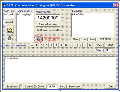
The PC software for the computer aided tuning
The code is written in the very old version Visual Basic 5. VB is still functionable, by the way 😉 . And it is not very complicated. All that you have to do is to pass the codes for the desired functions to the radio via the serial port. For first tests I used a simple terminal program and typed the codes by hand.
The more comfortable things with my software are functions that make tuning, changing frequencies and above all DX-clustering, possible by just a click. The user interface is pretty simple:
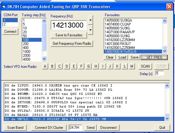
A complete package in ZIP-file format can be downloadad from here. Please notice that the file is named qrpcat.zi_ due to the fact that ZIP extension are not allowed on the server. So please rename the file as qrpcat.zip before processing it!
DX-cluster integration
I have to admit that I’m not the big enthusiast for clusters. I prefer to listen to the band. But it was interesting to achieve a direct transfer from a cluster reported frequency directly into the transceiver. Besides I learned a lot about the principles of these systems the last two days.
The basics first. In brief: DX-clusters form a worldwide net of servers exchanging data. This means that one DX station that is put into one cluster server is transferred immediately to the others. The servers use the TELNET protocol which is a simple text-only communication protocol. Therefore cluster messages are in text form.
In my Visual Basic application I use the WINSOCK-control to establish a communication between my computer and the cluster server.
WINSOCK is a universal control available in Microsoft Windows software (for VB and C++ as far as I know). The routines presented here are very simple and not 100% fool-proof. They are more for learning, even if they work well.
First thing you have do is to connect to a DX cluster. This requires a server name only. No password is neccessary for the one given in the server statement:
Private Sub cmdTNConnect_Click()
   If
     wskTN.State = sckClosed Then
     wskTN.RemotePort = 23
     wskTN.RemoteHost = "n7od.pentux.net"
     wskTN.Connect
   End If
End Sub
It’s very simple and merely to show you how it works. There is no error checking because I don’t want to confuse you. Use a push button to activate the code!
Normally the cluster responds with a “welcome” message to this opening . By the end of the message you must enter your callsign. Use this function to transfer the requested data:
Private Sub cmdSendTN_Click()

    If wskTN.State = sckConnected Then
        wskTN.SendData txtSendTN & vbCrLf
    End If

End Sub
txtSendTN is the text field the data is read from. Put your call in there! sckConnected is defined in a library and states that you are connected to the server.
So, this is all that had to be done to connect you to the server and to send some basic data. Now you just have to lean back and read the DX data that is transferred from the cluster host. To get this into a string variable, you have to use the DataArrival-method of the WINSOCK control. Some globals have to be declared first:
Global strTNRcvd As String
[...]
Private Sub wskTN_DataArrival(ByVal bytesTotal As Long)

  Dim strData As String
  Dim strResult As String

  wskTN.GetData strData

  strTNRcvd = strTNRcvd & strData
  If InStr(1, strData, vbCrLf) > 0 Then
      lstDX.Additem strTNRcvd
      strTNRcvd = ""
  End If

End Sub
Instead of lstDX.Additem strTNRcvd just do something useful with the received information. In my software I filter the frequency (only stations on the 20 meter band are interesting for my radio), extract the callsign and put this combination into the list of favourites. Just load down the ZIP file and see on your own.
So, that is all so far about the project “The QRP transceiver goes software defined”. If you have any questions, don’t hesitate to mail me: peter.rachow(at)web.de.
73 and thanks for reading!
Peter