Chapter 1: General design and oscillator circuits (This pageing)
Chapter 2: Receiver (coming soon)
Chapter 3: Transmitter (coming soon)
Chapter 4: Cabinet, frequency counter, antenna etc. (coming soon)
Chapter 5: Final remakrs (coming soon)
This radio also is some sort of “rebuilt”. in 2015 I developed a handheld transceiver with about 5 watts of output power capable for use in the 20-meter-band (Link). The idea was great for hiking, traveling and cycling tours. But the output power was slightly inferior particularly when using a shortened rod antenna. Also was the battery pack too small to provide sufficient energy for longer operation. These shortcomings had to be overcome because spring and summer season are approaching and I intend doing much outdoor activities in upcoming warmer weather conditions.
The design thus had to meet the following requirements:
- Output power set in the range of 10 to 20 watts pep.
- Powered by rechargeable batteries of sufficient capacity
- Size must be as compact as possible under the given technical data mentioned before
- The rig has to provide a rugged design for outdoor and field use.
- An antenna holder should be integrated into the cabinet to enable the operator to use a rod antenna in the field.
These expectations lead to the following design guidelines:
- Four stage transmitter with driver and final stage in push-pull mode.
- A set of 11 nickel-metal-hydride solderable AA cells with the possibility to charge while mounted in the radio (no need to open cabinet for recharging process).
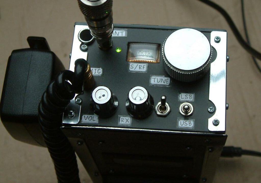
- Size of about a vintage CB hand held transceiver of the 70s.
- Construction made of aluminum sheet metal and aluminum bars (equal leg structural angle).
For energy saving purposes I decided not to use any microcontroller or digital equipment. The radio is based completely on analog technology except from a ready made frequency counter purchased in the late 80s in the last century. The counter has been added because the main oscillator (VFO) is varactor tuned and this does not allow to use a simple frequency readout that would be possible when using (for example) a vernier reduction drive.
The Oscillators
This time we will start with the oscillator sections. As standrd with radios that use one interfrequency we use 2 oscillator: A VFO for main tuning and an LO for providing interfrequency range signals to produce SSB signal for transmit mode and to demodulate received signals.
The VFO
I am running out of vernier drives. 😉 Two most practical main solutions that remain for setting the frequency in a VFO are either a permeabiilty tuning (by inserting some ferro- or diamagnetic metal into the coil and thus changing inductance) or by making use of a varactor. Because the first method involves a lot of mechanical challenges to ensure stable operation and therefore has been considered not being achiveale the decicion was to use a varactor tuned VFO.
The VFO is Colpitts type:
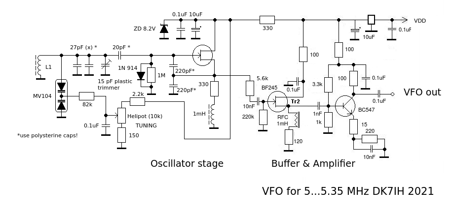
Design hints:
- Main coil is made of 50 turns of 0.2mm enameled wire on a T-37-2 toroidal core. I used the Colpitts design this time because without a tapped coil (as required for the Hartley design) experimenting is easier when to determine the exact number of turns.
- The varactor is a MV104 type (purchased via ebay). This one is used as tuning device in AM radios or so and works fine because it provides high capacity swing with low DC voltage span.
- The “fine art” of building this oscillator is to spread the 10 turns of the helipot so exactly that the full band from 5.00 to 5.35 MHz is coveren and wasting any space (except from 1 or 2 kHz for each edge) is avoided. The possibilities you have are modifying the two resistors (2.2k and 150 ohms), changing the number of turns in the coil ans, at last, changing the capacitors (27pF) and setting the trimmer value properly at last.
- Fixed capacitors in the first stage of the VFO should be polystyrene (best choice) or NP0. Polystyrene caps, according to my findings, inherit contrary temperature coefficient compared to the material of the coil (iron powder), therefore excellent frequency stability of this oscillator is achieved. In practical the oscillator needs 1 or 2 minutes to warm up and subsequently drifts with some 10 kHz per hour.
To my consideration it is not necessary to install the VFO into a separate cabinet or shielding because it is, as mentioned before, absolutely stable concerning frequency. But, as you guys all know, it is not the best idea to place it right next to the final RF amplifier stage ;-).
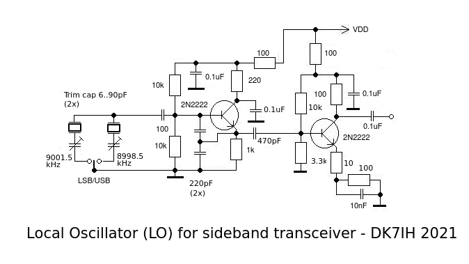
The Local Oscillator
This oscillator also is a Colpitts one. Two crystals (9001.5 kHz and 8998.5kHz) are switched by a two position switch in the front panel. The oscillator is followed by 1 amplifier stage putting out about 1 Vpp.
(To be continued…)
Thanks for watching! Peter (DK7IH)
DDS “oscillators” can have less phase noise than VFO’s, though maybe not a big issue in a portable rig. Power requirements for microcontrollers are not an issue, newest ones can sleep at nano amps, and wake up on interrupt when encoder knob is turned. I don’t think I’d ever design another rig using an analog VFO again, accuracy of digital is too good, and calibration a snap.
Another nice design! Circuitry similar to one of my designs from the 1980’s as published in Ham Radio Magazine. Keep up the good work.
73, Jim WA3TFS
http://wa3tfs.com
Hi Peter,
Good to catch up on this revamped analogue hand held. One minor thing I can see, the local oscillator trimcaps in series with the BFO crystals, if you place them on the earthy end rather than the ‘hot’ end, you can tune them without hand and tool capacitance pulling the oscillator frequency.
Good luck with this!
73 Paul VK3HN.
Hi Paul, thanks a lot! And, yes,that’s the way I do it. The schematic is false under this respect, have to update it. 😉
vy 73 de Peter (DK7IH)
DR OM!
What about the other stages of your transceiver? Your nice constructions always full of brilliant ideas. l’m waiting for them. TNX de HA8LUA, Aron
Hello OM Aron, thanks a lot for your mail. The other stages are relatively the same like those in the High Performance TRX for 20 meters:
https://dk7ih.de/constructing-a-high-performance-transceiver-for-voice-communication-on-14mhz/
The purpose of the hand-held radio mainly was to find out if a varactor tuned vfo would be reasonable stable to perform qsos from a portable radio.And, now I know, it definitely is. 🙂
Vy 73 de Peter
Dear Peter!
A nice rig again your 14MHz & up walkie-talky! I’m just building (very-very slowly..) a little 7MHz CW TRX. I’ve tried many stages from you (i.e. MOS-FET mixers, IF amps, etc.). They usally worked fine in many combinations. Because of having very little space in it’s box (scrapped old mobile CB cabinet), I planned to use the NE612 as product detector. As I saw your constructions appeared a question for me: what is the reason why you never use the NE612’s internal oscillator stage as BFO? It would be useful to save a lot of space in my little box. Maybe this seems to be a silly question, but I’m not so professional homebuilder like you.
TNX & Vy ’73! de Aron (HA8LUA)
Hello Aron,
thanks a lot for your compliments and your question. The answer is simple: First, I have used it sometimes. 🙂 But in earlier time, like in this radio:
https://dk7ih.de/wp-content/uploads/2015/02/20-meter-14-mhz-ssb-transceiver-by-peter-rachow-dk7ih-pcb.jpg
You can see a crystal (marked with red color) next to an NE612 mixer IC.
Second, I have found that it was pretty weird to select the respective sideband by using a single crystal for USB and another one for LSB with precise results. A switch in the front panel or even with a relay close to the crystals, all did not work precisely. This is because the oscillator in the NE612 is very sensitive and takes what ever capacity or inductance it can take to include the frequency determining element(s) into frequency generation. These parasetic capacities lead to incoupling the “wrong” elements, the “opposite” crystal (basically unused in that situation) always interfered with the “used” one. So, these oscillators never were exactly defined concerning frequency. They “swapped” frequencies deliberately leading to sponatenous sideband changes while operating. On the other hand: When you use only one crystal, it works. But as I prefer to make both sidebands switchable this was a severe shortcoming of the integrated oscillator. Thus I use it very rarely. Another thing is that when you use the Si5351 for example you have 3 oscillators on the chip, which are more than I need. They can be easily controlled by software, no hardware is needed.
Hope, I could answer the question sufficiently… 😉
Vy 73 de Peter
I use the local osclillator generally for receive AND transmit purposes because my radios are made for SSB. With a CW rig, where no DSB generator is included, the need for an external oscillator does not exist because you transmit more or less (except from some hundert Hz shift) on the same frequency.
DR Peter OM!
Thanks for the quick and detailed answer!
’73! de Aron
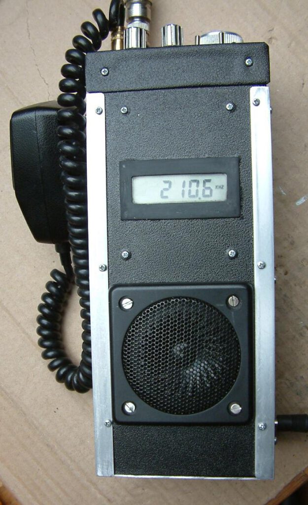
The frequency displayed, is in the Long Wave band ? ,not 21 megs band.the dot is in the wrong place.
It only seems so. The counter is an off-the-shelve unit and allows only a small number of pre settings concerning interfrequency setup. Thus I used it to display only with the relevant digits except from the leading “14” digits.
Vy 73 de Peter