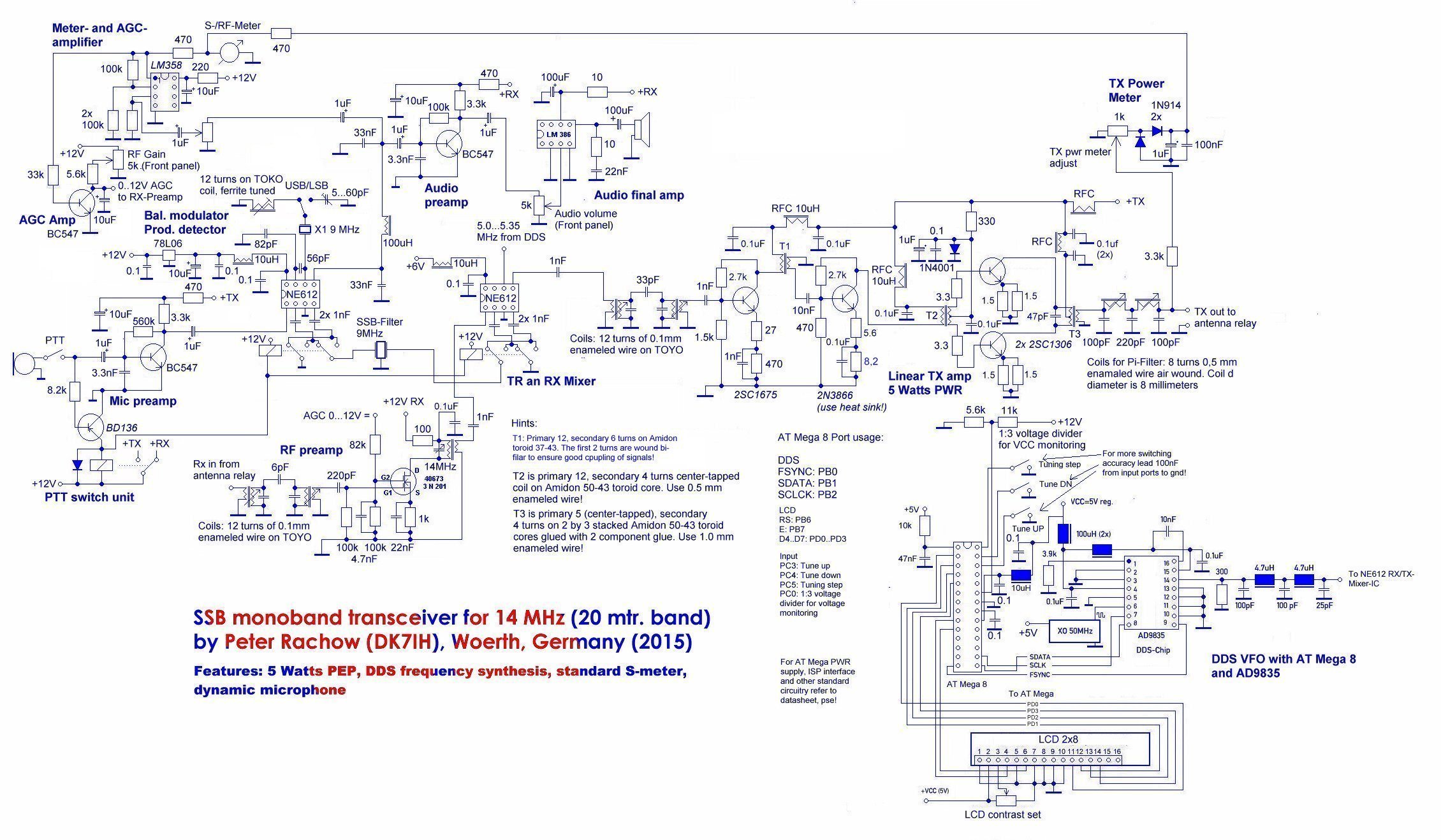
This is a very compact SSB transceiver for the 20-Meter Band. This band is still my favorite band for QRP operation. The objective of the design were to be compact in size, 5 watts PEP output, a single conversion superhet, DDS-VFO and SSB (phone) operation only.
The circuit is based on the common “2-Mixers-1-Filter” design which I adapted for 20 meters. The receiver has been given a pre-amp stage using a dual-gate MOSFET to improve the signal-to-noise ratio and to increase the overall gain. The rest is more or less a QRPer’s classical “business-as-usual”. Well, maybe except from the frequency control. This is done by the well-known DDS-chip AD9835 which I now often use driven by an AT mega 8 microcontroller.
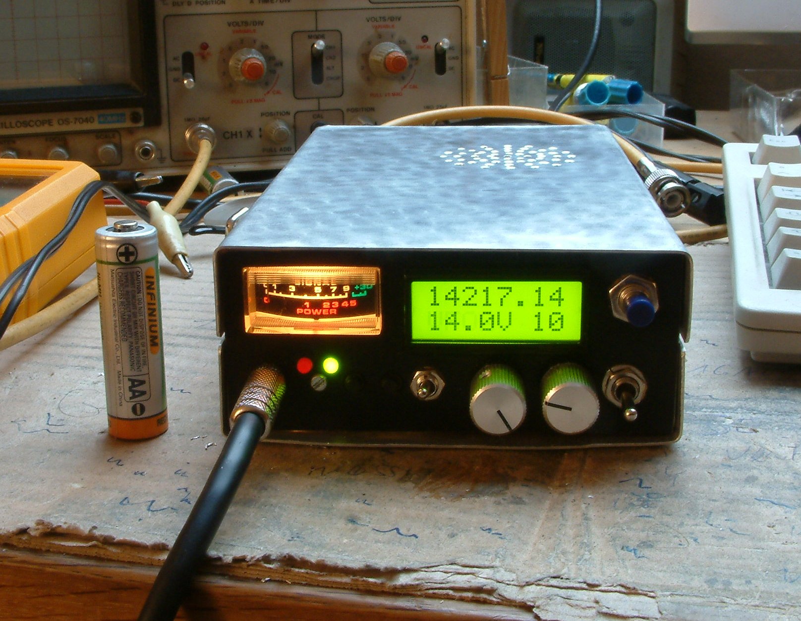
Here’s the rig in a homemade cabinet made of aluminum and copper plated pc board. Notice the AA-sized battery to the left for size comparison.
The circuit, as mentioned before, doesn’t have loads of features, but the transceiver performs very well in spite of the simple circuitry.
Some technical annotations should now follow:
Frequency generation and tuning:
As mentioned before: Frequency generation is done by a AD9835 DDS chip that Is controlled with an ATmega8 microcontroller. There is no rotary vfo knob on the rig. Instead I use an UP-DOWN-switch with one neutral and two switching positiones. One for “up”, one for “down”. In addition the tuning step can be manually set so that you can easily tune the band using various speeds. The minimum step is 10 Hz. Next steps are 20, 50, 100, 250, 1k, 2.5k and 5k. After you have tuned with higher rate than 10 Hz the step is reset after 4 seconds of idle time automatically to 10 Hz.
Receiver sensitivity:
AGC is controlled by an operational amplifier (LM358). The input signal is derived from the audio after the audio preamp. The output of the LM358 goes to an NPN transistor regulator that is in the positive voltage line from the manual gain control accessible to the operator. The LM358 also drives the S-Meter.
PTT:
I use a one-line-ptt. The base of a PNP-transistor is lead thru the microphone to ground in case the ptt is pushed. This swithes the transceiver from receive to transmit mode. The microphone jack is a 3 pin standard stereo earphone jack with 3.5 mms diameter. The remaining line switches the loudspeaker. This is done because the capacitors of the LM386 audio amp discharge too slowly and this causes some feedback of about a quarter of a second when the ptt is pushed.
Sideband generation and switching:
Some internet sites state the NE621 should not be a good choice for generating an ssb signal in a transmitter using the filter method. Builders particularly say that suppression of the carrier and unwanted sideband is inferior to other common mixer circuits like the MC1496. I defenitely cannot confirm this. After having built a dozen ssb rigs in the recent years with all the technologies and parts available to the amateur (diode mixers, MC1496, CA3028A, dual-gate-MOSFET etc.) I have never had a rig that allowed a carrier suppresion of >50db like in my mini QRP transceiver that is described here. The NE 612 is a faboulus sideband generator. Give it a try!
But where there is light you can also see the shade: One problem with this rig was sideband switching. After having used 2 different crystals for the USB and LSB I found that under certain conditions the LO did not go to the desired frequency. After long hours of experimenting I discovered that sometimes the 2 crystals were resonating simultanously. The NE 612 integrated oscillator starts to oscillate very early and can produce signals even if the crystal is verly loosely coupled. A few picofarads are enough! The capacities inherent in each circuit are sufficient to make the NE 612’s LO oscillate like a crystal. So in my setting the crystal for the sideband that was not switched by a time also was running by to produce the LO signal. But it did this unwantedly. And to my desperation.
Therefore instaed using a 9.0015 and a 8.9995 MHz crystal, I removed the two crystals and used one for 9.0000 MHz. This one is pulled switchable with either a capacitor or a coil (20 turns or so) to get to the desired frequency. Look to the schematic to find out the details. Now this works absolutely fine!
Performance of the SSB-Transceiver:
The rig is big fun! With 4 to 5 watts I worked all over Europe within a few days. My antenna is also very simple. A dipole with its apex 10 meters or so above the ground. Not really “big guns” as you can imagine! My signal reports say indicate that the transmit audio is very clear.
The receiver is sensitive and has a good noise figure. You can pick up even ZLs and VKs even if you can’t work them. Think I have to make some antenna improvements to get my first VK with this rig!😉
See u soon!
73 de DK7IH (Peter Rachow, Woerth, Germany)
(Thanks to Craig, KD2CXK, for reading the text and improving the English language!)
I’m very interested in learning more about your two 20M QRP transceivers. I’d like to build one myself, perhaps adding an MC1350 IF stage to the little guy. Do you have schematics for the larger rig?
Hi Kennth,
sorry for answering so late. I don’t check the entries here regularely. For the larger rig there is no schematic. Sorry to say so!
Best 73! de Peter (DK7IH)
hi
i really impress your design for higher bandwidth operation. i am very glad if your help to make a full deplux transceiver its my final year project.
thanks
the like it, here in brazil, very good! ok ,mosfet bf 892,(6), mc1350 (5) , lm 386 or lm 380, bf 494 (10), the best receiver in lsb, dsb, usb, am. filters 7157 mhz (12)….sen .0.01 uv! parametric amplifier, ok by.
Thanks for your personal marvelous posting! I genuinely enjoyed reading
it, you could be a great author.I will always bookmark your blog and will eventually
come back very soon. I want to encourage you to ultimately continue your
great posts, have a nice morning!
Ok, I like of circuit is very simple, here in Brazil ,I used pre amplifier ( 6 X,) BF 982, ,BC 549, BC 550, power amplifer IRF 510, (3x) MC 1350, ,coolér peltiér in P A, temperature 1~6 Cº, <<noise.
Hallo Peter,
Ich habe mit Interesse Deinen Artikel und die Kommentare gelesen . Ich suche für SSTV einen einfachen Transceiver, der minimal 1 Watt abgeben kann, um eine Mini-Pa an zu steuern.
Kann ich so ein Gerät käuflich erwerben und wie wäre der Preis ?
Hallo Peter,
Ich habe mit Interesse Deinen Artikel und die Kommentare gelesen . Ich suche für SSTV einen einfachen Transceiver, der minimal 1 Watt abgeben kann, um eine Mini-Pa an zu steuern.
Kann ich so ein Gerät käuflich erwerben und wie wäre der Preis ?
Hallo Martin,
leider verkaufe ich keine Geräte mehr. Der Grund sind u. a. die Überregulationen der deutschen Behörden und der EU, da für mich die Produktion und die Einhaltung der gesetzlichen Vorschriften nicht mehr kostendeckend wären. Tut mir wirklich leid!
Vy 73 de Peter
Hello, the software for atmega vfo?
Thanks
Hi dear reader, sorry to say that I have lost this software as the project is fairly old and I have changed my PC since then. But you can go to my Github repository where you can find lots of code for similar transceivers.
https://github.com/DK7IH
vy 73 de Peter (DK7IH)