In my junk box I found 2 transistors MRF 455, each capable of delivering 60 watts of rf power. I quickly made up my mind that I wanted to construct a useful circuit for these two high power rf transistors. A linear amp for my 5 watts 14 MHz QRP SSB transceiver was the goal I had to achieve in order to get a little more power for the tiny transceiver.
And, in addition, I also have had an amplifier strip of a blasted Atlas 215 transceiver for about 20 years that was destroyed because of using false polarity power supply. The only thing useful that survided this massive destruction were the broadband transformers for input and output. So why not trying the reconstruction of the famous PC500-board of the Atlas amp as a QRP linear power amplifier that can be used when band conditions are low and a few watts of extra power are needed?
So, here is the circuit of the PA:
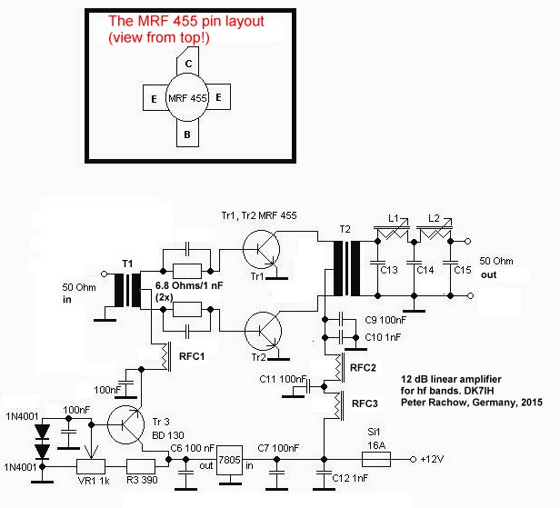
As you can see from the picture, the rf transformers T1 and T2 are made of big ferrite beads. The inlays are brass or copper tubes serving as rf leads representing secondary (T1) or primary (T2) winding. The tubes on one side are connected by a large solder bride serving as the tap of the winding. The primary of T1 are 3 turns of thick insulated wire, the secondary of T2 are 2 turns of the same material.
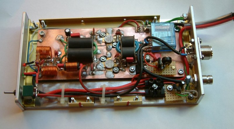
I built the amplifier on a copper plated pc board. The single solder pads are handmade using an electric mini drilling machine device carrying a small cutoff wheel. The remaining copper gives a suitable ground plane for the PA circuit preventing instabilities. More complex circuitry like the adjustment circuit for the idle current was conventionally made on a veroboard. Idle current should be set to 100 mA.
L1 and L2 in the final low pass filter are 9 resp. 10 turns of 1mm diameter enameled wire. Coil diameter is 8 mm. C16 is 68 pF, C14 is 120 pF and C15 is 100 pF. Each capacitor must be able to withstand 120 V at least! I recomend testing your own values!
What I didn’t point out in the schematic above is the relay that controls signal flow (it’s really trivial to wire that) and the hf vox which can be found on the internet in many variations.
The bottom part of the enclosure I constructed is made of 4 mm (!) aluminum plate. Due to the fact that I intend to use the PA for SSB only I did not use an extra heat sink. The cooling by the large and thick aluminum plate is sufficient for ssb operation. The whole body therefore became very slim.
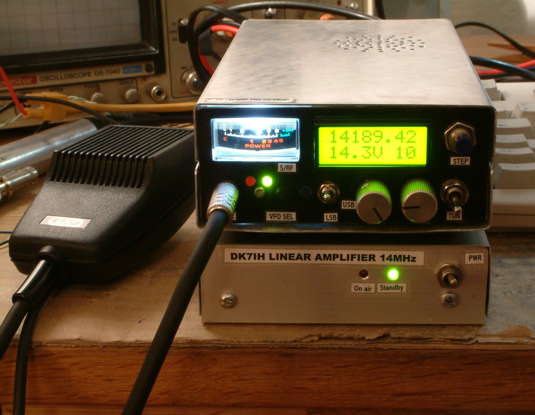
Driven by my 5 watt QRP SSB transceiver for 14 MHz the linear amplifier puts out about 60 watts in the peak with perfect signal quality. So I finally got a good new workplace for my surplus MRF 455s and the 2 rf transformers from a destroyed ATLAS transceiver I can use when “life’s too short for QRP”. 😉
Best 73 de
Peter (DK7IH)
(C) 2015 by Peter Rachow, DK7IH