This article is outdated! Please read about the new version of the antenna tuner here!
After I had finished my 5 band multibander for QRP SSB operation I had 2 choices becoming QRV on the hf bands – either to build up something like an antenna farm (which would have caused severe problems with my familiy 😉 ) or to build a multi band antenna capable of being used on all short wave ham bands. In order to survive the next months with more or less stable health I have decided to take the latter alternative.
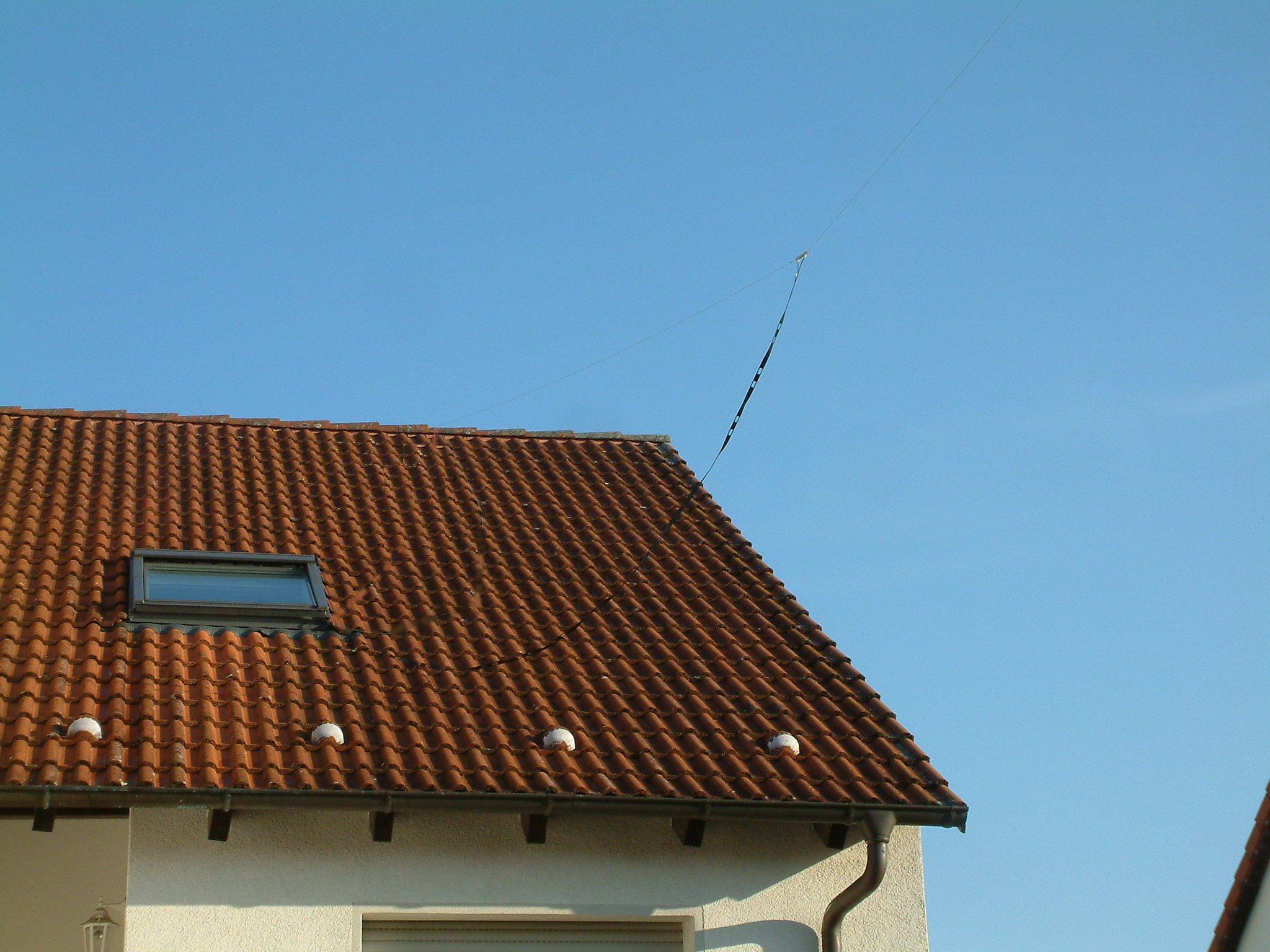
Browsing my good old antenna handbook by Rothammel I came across an untuned multiband dipole. This is known sometimes as a “doublet antenna“. It’s a simple dipole, fed by an open wire feed line which has to be matched to the transmitter for each band of operation. The length of one branch of this antenna is about a quarter wavelength of the lowest operating frequency which makes it a half-wave dipole for in my case 80 meters. On the internet I found lots of users of this antenna speaking positively about its performance, so I decided to give it a try. Antenna construction is very simple and the doublet antenna does not spoil the optical impression of your ground property seroiusly.
But one major shortcoming of this antenna should not be ignored: The “doublet” antenna can not be operated directly from coax line, it has to be matched for each band seperately to the desired frequency with its specific impedance to come as close as possible to the 50 ohm of the transceiver. Open wire feed line must be used because there is always a high VSWR on the feedline due to the fact that the dipole is not tuned to the operating frequency. But as losses are low in double wire line even if SWR is high, this is not a problem. Be sure that more than 95% of your transmit power will reach the antenna.
Due to the fact that my antenna installation requires only 5 to 6 meters of feedline from my roof window to the antenna’s feed point, I first built a ladder line from flexible cable and homemade acrylic spacers. But this tended to be a little bit service-unfriendly. Always whenI tried to pull back the antenna for modifications, the line (the spacers to say more detailed) got entangled in the roofing-tiles. So I bought off-the-shelf 450-Ohm Wireman line that does not show this problem.:
After having installed antenna and feedline, I first I built a simple L-match tuner for test purposes. If this antenna had not worked with me I would not have lost much time and money. But no need to worry. After having set up the antenna and the tuner I was quite satisfied. Performance was beyond my expectations. But with using this setup more often, I found out that retuning after having QSYed was not that nice. I had written down the settings for capacitor und inductance on a piece of paper so that they could be recalled relatively quickly. But it was not overwhelming conveniant. Thus my idea was: If you have the settings for each band on a paper table, why not putting them into a microcontroller and let the micro do the tuning?
The basic concept of the tuner
The tuner is an L-Match tuner that can match high Z antennas. Long antennas tend to have higher impedances than usually the 50 ohm transceiver’s output. Integrated into the tuner is also an SWR measurement circuit (directional coupler from old CB radio) so that an external SWR meter is not neccessary. The tuner is tuned manually. After matching has been achieved, the values for L and C are stored by pressing a button and can later be recalled by bandswitch. Retuning is easy. Just press buttons for L+, L-, C+ or C-, retune and store the modified settings. After that: Have fun in a QSO!
Coils
There are 6 coils in the tuner, switched (shortened) by 6 relays. The inductances are doubled (more or less) from one coil to the successor, so that in combination nearly each inductance between 0.5 uH and 39 uH can be switched. It turned out that this concept works fine. The single inductances are:
20uH, 10 uH, 5 uH, 2.5 uH, 1 uh, 0.5 uH
Coil data: Each coil except the smallest one is wound on a T80-2 Amidon toroid. Use 0.3 mm diameter copper enameled wire. The winding data:
- L1 (20uH): 60T.
- L2 (10uH): 43T.
- L3 (5uH): 30T.
- L4 (2.5uH): 21T.
- L5 (1uH): 13T.
- L6 (0.5uH, wound on T50-2 core): 10T.
Output transformer
Another coil must be wound because the antenna has an unbalanced circuit inside (1 coil, 1 cap). The feed line on the other hand is balanced, so this has to be kept in mind. To convert the unbalanced output of the tuner circuit to the balanced feeder line, I use a 1:4 balun at the output of the coil chain (T1 in circuit diagram). Wind 12 turns bifilar of 0.8 mm twisted (about 3 twists per cm) enameled copper wire to a FT114-43 Amidon core using this pattern.
Hint: On the picture below there is a balun transformer that I previously had installed. It was a Guanella balun but it did not perform satisfyingly. Tuning could not easily be achieved on 10 and 15 meters.
Capacitor
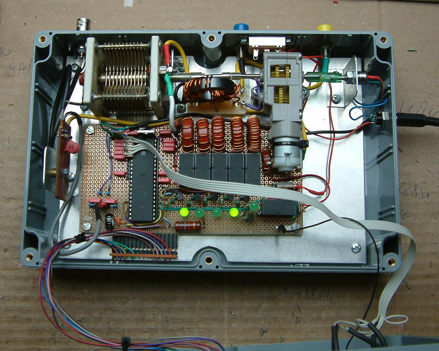
The tuner uses a motor driven air dielectrical and butterfly shaped capacitor with max. 220 pF capacity. The advantage of a butterfly type is that it needs only 90° to turn it from minimum to maximum capacity. The motor (a 5V dc version) is connected via a 240:1 gear drive by TAMIYA. The drive has two outlets providing one axle at each side of the drive. To one of the axles I connected the capacitor, the other one connects to a potentiometer to report the current swing angle to the microcontroller.This allows precise feedback of the capacitor’s current position which is essential for setting it to the desired value. The value of this variable resistor does not really matter since it is only a simple voltage divider. Anything between 5k and 100k should fit. Make sure that you use a piece that is easy to turn to minimize friction. To connect the axles I used PVC tubing with an inside diameter of 3 mm.
This is the setup:
Circuit
Here’s the schematic of the tuner:
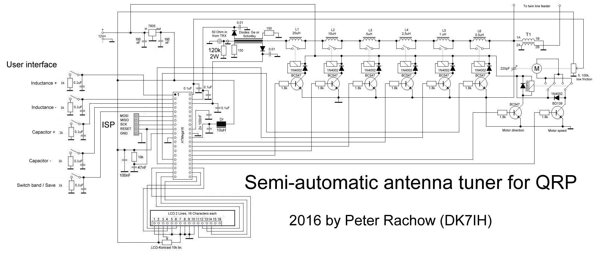
Right at the 50 Ohms input where the transceiver is connected you can see a 120 kOhm resistor. The purpose of this one is to keep static electricity away from your rig. Antennas with open ends (like the “doublet”) can build up high voltages particularly when strong rainfall coincides with heavy winds. The raindrops build up an electrical potential during their way through the clouds. I once have seen sparks of 1 to 2 cm of length in my shack when I brought the feed line wire of the antenna close to a grounded metal cabinet.
First impression of performance
I have been using the tuner for three weeks by now. My antenna has got a total length of 40 meters, height is from 10 to 12 meters above ground. Feed point is approximately centered. The antenna with this tuner allows operation on all the 5 bands of my QRP multibander. Signal reports are usually good. On 20m I receive 5 and 9 reports very often. Transmit power only is 10 watts. On 40m and 80m the same is true. Even 15 meters, usually not so fine on a 40 meter long doublet, works fine. 10 meters has not been tested yet due to band conditions.
Maximum distance so far was to W2YP (East coast NY) with my rig having 10 watts output on 25th February receiving a 57 report.
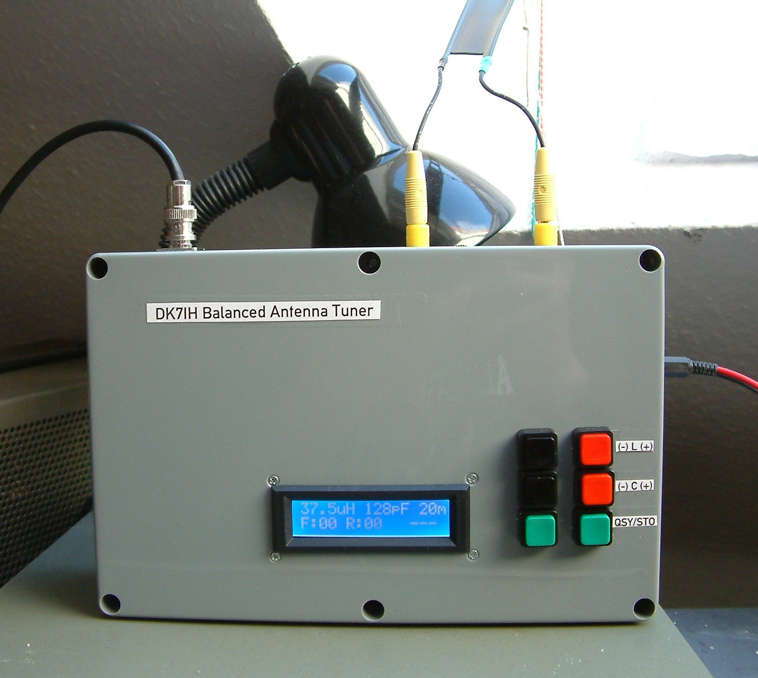
Enclosure
I used a simple plastic box that is available for eletrical installations. RF leads are on top:
Software
I’m currently doing some improvements concerning software. If you are interested in the software, please drop me a mail: peter.rachow(at)web.de !
Enhancing the tuner
This tuner mainly for matching long wire antennas which have a comparatively high Z in relation to the 50 Ohms of a radio tranceiver. If you also want to match low Z antennas (shorter than 1/4 wavelength), the capacitor must be put to the opposite of the coils:
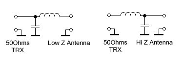
If you would like to have the capacitor in place for switching between hi an low Z antennas another relay will do the job. The microntroller has still plenty of usable ports.
Thanks for reading!
Peter (DK7IH)
looks great
very nice indeed
Baruch 4z4rb
TNX a lot! 😉 vy 73 de Peter
I like the binary sequence of series connected inductors. I might have used a stepper motor to drive the capacitor, if fitted with an end position sensor (photo diode, led, interrupter) the processor could return to stored positions automatically. Then auto seek functions by reading the SWR with the A/D stage could be added. For finer inductance settings a stepper driving a varometer (two series connected planetary coils, one fixed, one rotates) could be used instead of the smallest inductor (air core). Keep up the homebrew, I hope to build a transceiver using your ideas.
Yes, Ken, actually the capacitor drive motor works like a stepper motor. It is driven by the microcontroller applying short pulses so that every pulse changes the capacity to some picofarads. After each pulse the new capacity is measured. This is, as I found out, sufficient for precise tuning. I considered an automatic tuning routine in the beginning of the project to be programmed to the software. But then I found out that manual tuning is very easy and due to the fact that I use this tuner only with my home station any sort of automatic tuning would not make that sense. I thus simply programmed the tuner in a way that the last settings can be recalled by just pressing one button to change band and that’s all. When I maybe once will use it for portable operation I conceive just adding a second or third collection of L and C settings to the software so that I have one fixed station set of values and one or two portable settings. Let’s see how it will finally work out. 😉
Meanwhile I’m quite satisfied with the tuner because I could work some of you US hams on 20 and 15 meters with my 10 watts of output and relatively good reports.
Thanks for reading my pages and good luck when building your transceiver. 🙂
73 de Peter (DK7IH)
Hi. your theme does not seem to show up properly under the web browser xxxxxxxxxxxxxxx version 68 I suspect its a problem coming from WordPress or your WordPress theme
[Non amateur radio related weblink deleted]
I just wonder how stupid you think I am. The Google search words and your web adress in your comment have been deleted. And don’t try this again!
Can you please share the compiled hex code with me. (coskunmuti@gmail.com) Thanks. 73 de TA2UCM