The next step in improving my homemade QRP multiband transceiver was to reconstruct the DDS VFO. This was not urgently neccessary but after some months of continously operating the rig I was not 100% satisfied with the spurious performance of the AD9850. The AD9850 is a DDS device with only a 10-bit digital-analog-converter (DAC). These ones tend to put out still a quite high number of spurious emissions aka “birdies”.”Birdies” then are detected in the receiver causing unpleasant beep tones.
The AD9951 DDS module (some general information)
Analog Devices (AD) also offers more professional DDS-chips with a better performing 14-bit DAC. The AD9951 is such a device. It is offered for about 25 USD by mouser.com and other vendors. It is also used in off-the-shelf ham band transceivers thus we can deduce that performance is improved compared to the cheaper DDS devices made by AD.
The AD9951 needs multi supply voltages, i. e. 3.3V and 1.8V. Digital inputs are 5V-compatible if 3.3V as D_VDD_IO input voltage is applied. The device can be clocked up to 400Mhz. If you use a clock generator with lower frequency, an internal clock multiplier can be used. But this deteriorates phase noise to a certain degree. For my VFO which works in the range only from 13 to 20 MHz I use a simple standard 5V 120MHz clock generator and I do not use the internal clock multiplier. To make the clock oscillator’s output 1.8V compatible a simple voltage divider has been applied.
Note that performance concerning phase noise of the DDS also depends on the voltage of the clock generator. The lower it is, the more the phase noise performance will deteriorate. To calculate exact configuration of your voltage divider keep in mind that input impedance (1.5 kΩ according to datasheet) and input capacitance (3pF) are paralleled. Input capacitance causes reactance depending on the input frequency given by the following equation:

Output circuit
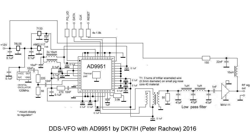
As usual for me the DDS output consists of a balanced-to-unbalanced broadband transformer followed by an rf amplifier. For the latter one I use the MAV-11 broadband amplifier made by Minicurcuits.
This the circuit of my improved DDS device:
Performance
The first impression when I connected the AD9951-DDS to my HP 8558B spectrum analyzer was that the signal looked different compared to a AD9850 generated signal. I’m very sorry, but so far I’ve got no photos but I’m planning an article that will deal with DDS comparisons which will have photos of the spectrographic analysis of the various signals. But it was visible on the first sight, that the signal looked much cleaner than a one produced by a DDS with 10-bit-DAC.
OK, there were much lower sidetones to the main signal on the spectrum analyzer. Measurements are one side of the medal, but how would the DDS perform in the receiver? It approved to have improved when I installed the new DDS into the transceiver and listened to the bands. “Birdies” have vanished to nearly 100%, only some very weak spots are discernable. And the receiver noise also seems to have lowered by a certain degree. But I don’t have measured that so far. Measurements are still to be done. OK, let’s check it out the following days (20 meter is very quiet today!) and then I will be able to say if and how the 14-bit DAC.
So, if you want to get the best performance (low number of spurs, low phase noise) out of the AD9951, here are some basic hints:
- Stay away far from the Nyquist-Frequency of the chip! Basically this is one third (33%) of the clock rate. I recommend to lower this down to one fifth. So, if you use a clock rate of 100 MHz, don’t let the DDS produce more than 20 MHz!
- Don’t use the internal clock multiplier! Use a clock generator with the highest possible frequency!
- Use a clock generator that will put out 1.8 Volts pp!
- Keep ground leads on your pcb as wide and short as possible!
- Decouple AVDD, DVDD and DVDD_I/O effectively!
- Set DAC_RSET to a value that DAC current stays lower than 10mA. 3.9k is a recommended value.
Practical implementation
The DDS is mounted to a small piece of veroboard using a 48-lead breakout-board for TQFP48 ICs:
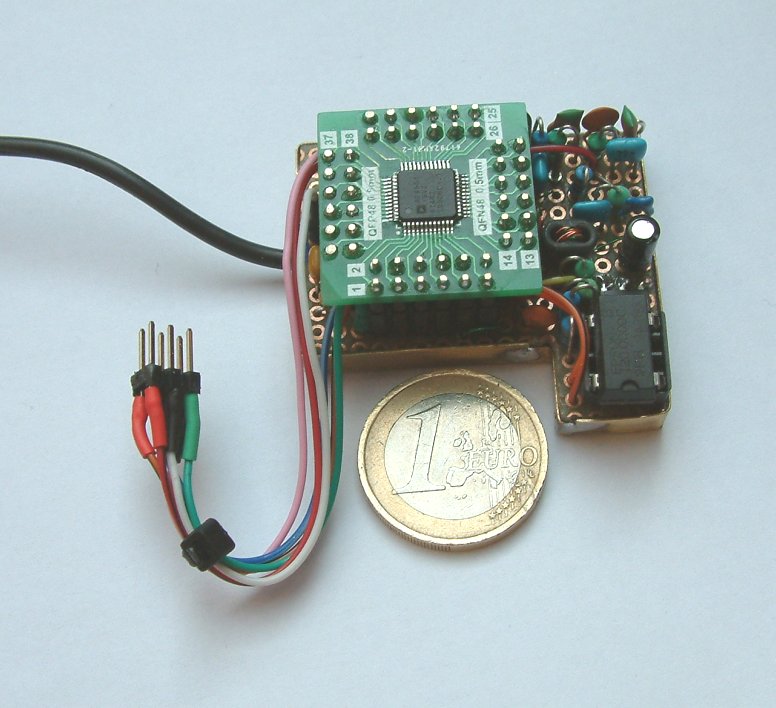
Flexible wiring is used to connect the board to the microcontroller. Shielded cable is mandatory for connecting the rf feed to tx and rx mixers.
Underneath you’ll find some code snippets to set the frequency of the AD9951 device. The code has been copied 1 by 1 from my SSB transceiver’s software. Thus modification for your purposes might be neccessary.
After inspiring discussion with a reader of my blog I’ve changed the routines to optimize code concerning performance. The major objective was to avoid intense use of floating point functions because they are slow. Instead I used bitshift operations widely. But there is one floatingpoint calculation left:
fword = (unsigned long) frequency * 35.790648;
The floatingpoint constant 35.790… results from a division of 0xFFFFFFFF by f_clock which is given by the equation of the tuning word (see datasheet of AD9951). This could be converted to a bitshift operation too, if you use a programmable clock oscillator tuned to 134,217,727 Hz. Then the multiplication factor is 32 which can be easily achieved with another bitshift operation.
Thanks for reading!
Peter (DK7IH)
Setting the AD9951’s frequency output
void set_frequency(unsigned long frequency)
{
    //PORT usage
    // FQ_UD:  PD0 (green)
    // DATA:   PD1 (white)
    // CLK:    PD2 (blue)
    // RESET:  PD3 (pink)

    unsigned long fword;
    int t1, shiftbyte = 24, resultbyte;
    unsigned long comparebyte = 0xFF000000;

    //Calculate frequency word
    //Clock rate =  120002500
    //0xFFFFFFFF /  120002500 = 35.790....
    fword = (unsigned long) frequency * 35.790648;

    //Initiate transfer to DDS
    PORTD &= ~(1); //FQ_UD lo
    //Send instruction bit to set fequency by frequency tuning word
    spi_send_byte(0x04);

    //Calculate and transfer the 4 bytes of the tuning word
    //Start with msb
    for(t1 = 0; t1 < 4; t1++)
    {
        resultbyte = (fword & comparebyte) >> shiftbyte;
        comparebyte >>= 8;
        shiftbyte -= 8;
        spi_send_byte(resultbyte);
    }
    //End transfer sequence
    PORTD |= 1; //FQ_UD hi
}

//Send one byte to DDS
void spi_send_byte(int sbyte)
{
    // PORT usage
    // FQ_UD:  PD0 (green)
    // DATA:   PD1 (white)
    // CLK:    PD2 (blue)
    // RESET:  PD3 (pink)

    int t1, x = 0x80;
    for(t1 = 0; t1 < 8; t1++)
    {
        //SCLK lo
        PORTD &= ~(4);          //Bit PB2 set to 0
        //Set respective bit to 0 or 1
        if(sbyte & x)
        {
             PORTD |= 2;  //SDATA Bit PB1 set to 1
        }
        else
        {
             PORTD &= ~(2);  //SDATA Bit PB1 set to 0
        }

        //SCLK line set to 1 // = set clock line to RISING edge to store bit in frequency word
        PORTD |= 4;  //Bit PB2 set to 1
        x >>= 1; //Shift bit to divide x by 2
    }
}
Resetting the AD9951-chip:
(A reset must be performed once immediately after your program was started and before you
transmit the first instruction to the AD9951 DDS chip)
void reset_ad9951(void)
{
    //PORT usage
    // FQ_UD:  PD0 (green)
    // DATA:   PD1 (white)
    // CLK:    PD2 (blue)
    // RESET:  PD3 (pink)
    PORTD |= 0x08; //Bit PD3 set
    _delay_ms(1); //Hold reset line hi for at least 20ns.
     PORTD &= ~(0x08); //Bit PD3 erase
}
(C) 2016 DK7IH (Peter Rachow)
You are using floating point math to calculate the DDS frequency word. The floating point libraries on the AVR take up a lot of space and are slow. It is possible to use integer math and some tricks, here is how I did it for an AD9851:
// (2^32 / DDS_CLK) + (remainder( (2^32 / DDS_CLK) * (2^24)) gives
// 32 bit binary floating point IIIIIIII.BBBBBBBBBBBBBBBBBBBBBBBB
// re-calculate K if the clock frequency is different
// will need a calibration method
// (2**32 / 180000000) + (rem of 2**32/180000000)*(2**24)
//above assumes integer division.
//If done on calculator perform the following
// ((2**32)/ddsclk) * (2**24) is necessary,
//convert result after rounding to next whole number to hex.
// generates a binary floating point number as an integer
#define Konst (unsigned long)0x17dc65de //Hex representation of binary floating point representation of
#180,000,000
//Konst is a 32 bit number, but is stored in a 64 bit variable
//because it will be multiplied by a 64 bit number
union K
{
uint64_t K64;
uint32_t K32[2];
}K;
// perform a floating point mult of the frequency by the
// dds constant for 180mhz clock and a 32 bit accumulator.
// Integer math is performed and the fractional portion
// of the result is shifted away.
unsigned long CalculateDDS(unsigned long freq)
{
union dds{
uint64_t Product; //64 bits
uint32_t Part[2]; //32 bits * 2
uint16_t i[4]; //16 bits * 4
}dds;
//store the 32 bit frequency number as the low half of a 64 bit number
dds.Part[0] = freq;
dds.Part[1] = 0;
//multpliy 32 bit frequency by 32 bit constant to get 64 bit number
dds.Product *= K.K64;
//shift left to remove fractional part of result
dds.Product = dds.Product << 8; //shift left one byte
//result is the integer part of the result. We have
//performed a floating point multiply using integer math.
return dds.Part[1]; //return upper long int as result
}
Left out one little thing:
// in init section of code …
K.K32[0] = Konst; //initialize Constant storage.
Thanks very much for your contribution! Will try that soon. Maybe useful for other visitors, too! 73 de Peter
I’ve revised the code for the set_frequency() function a little bit by picking up some of your ideas:
– Use a fixed value for 0xFFFFFFFF / fclock by calculating this once an writing it to a constant,
– use bitshifts instead of integer division
73 de Peter
Dear Peter, I have a problem in supplying crystal oscillators. If we use 30 Mhz instead of 120 Mhz, how do we make a change in the code?
In line
fword = (unsigned long) frequency * 35.790648;
you must replace 35.790… by 143.166 (0xFFFFFFFF / 30000000 = 143.165576533)
Problem: This won’t work for higher output frequencies because then you are very close to Nyquyst frequency. I recommend using a 75MHz oscillator minimum!
73 de Peter
0xffffffff /75000000= 57.2662306 true?
Yes. The calucaltion is OK. 73 de Peter (DK7IH)
Dear Peter, what can I use instead of mav11 in the dds circuit? I can’t find the Mav11 transistor.
TA2ITA 73
Hi Taskin, MAV-11 is not a transistor, it is a 3-staged monolithic amplifier. Minicircuits.com is the manufacturer. An alternative in case that the IC is not available, is ERA-3. Vy 73 de Peter