On one hand sunspot cycle is on the decline. Conditions on the higher bands tend to deteriorate gradually. On the other hand I wanted a very compact transceiver for outdoor (particularly holiday) activities. Besides this and due to the fact that I prefer monoband operation when on tour, the potentially ideal band had to be found. Based on these prerequisites I made up my band to go to 40 meters for this project.
Some interesting concepts for QRP-transceivers for this band can be found on the web. The “Santerre” and the “ILER40” should be mentioned. These operate with power levels of about 5 watts which I thought should not be enough in most of the situations. My opinion is, that on 40 meters it’s not the best decision to operate on the standard QRP watt level, e. g. like the mentioned before and my other rigs have been designed for. With high probability you’re about to get lost in the naturally higher band noise and QRM that is around on 7 MHz. Thus, 50 to 70 watts possibly should be a more suitable power level to operate on.
Basic concept
From the electronic point of view this transceiver doesn’t involve very much new stuff. The 4-stage transmitter with push-pull driver and final from my multi-band rig with emitter degeneration circuitry in every stage to improve linearity but without negative feedback in this circuit. Some NE612/SA602-mixers in receiver and transmitter, MC1350 as the rx’s if-amplifier, LM 386 as audio amplifier, busines as usual. DDS with AD 9551 for frequency generation. No fuss, no SDR-stuff. “Old school” homebrewing. Not more, but not less.
The challenge this time was to increase package density once more to an achievable maximum. The maximum size I wanted to have was the size of a carton of cancer sticks, also known as “cigarettes”.
Another problem of the project was to get a high power rf amplifier with an output level very much beyond standard QRP and avoiding any unwanted coupling, parasetic oscillations etc. even when components are very densly packed. A clean signal is a must, not of the package size.
Construction principles
The center of the construction is made of the aluminium carrier of the 50 to 70 watts final that is in the center of a three layer arrangement consisting of
- receiver board
- rf power amplifier
- rf board with SSB generator, tx mixer, pre-amp, pre-driver and driver (push-pull).
The parts of this assembly:
The main frame carrying all the other stuff:
Dissambled mounting frame of QRP transceiver for 40 meters (2016 by DK7IH)
The aluminium plane centered will keep the PA 50 to 70 watts board. This one is equipped with two MRF455 rf power transistors made by Motorola.

Above and below this board the receiver and transmitter boards are mounted to a three layer package.

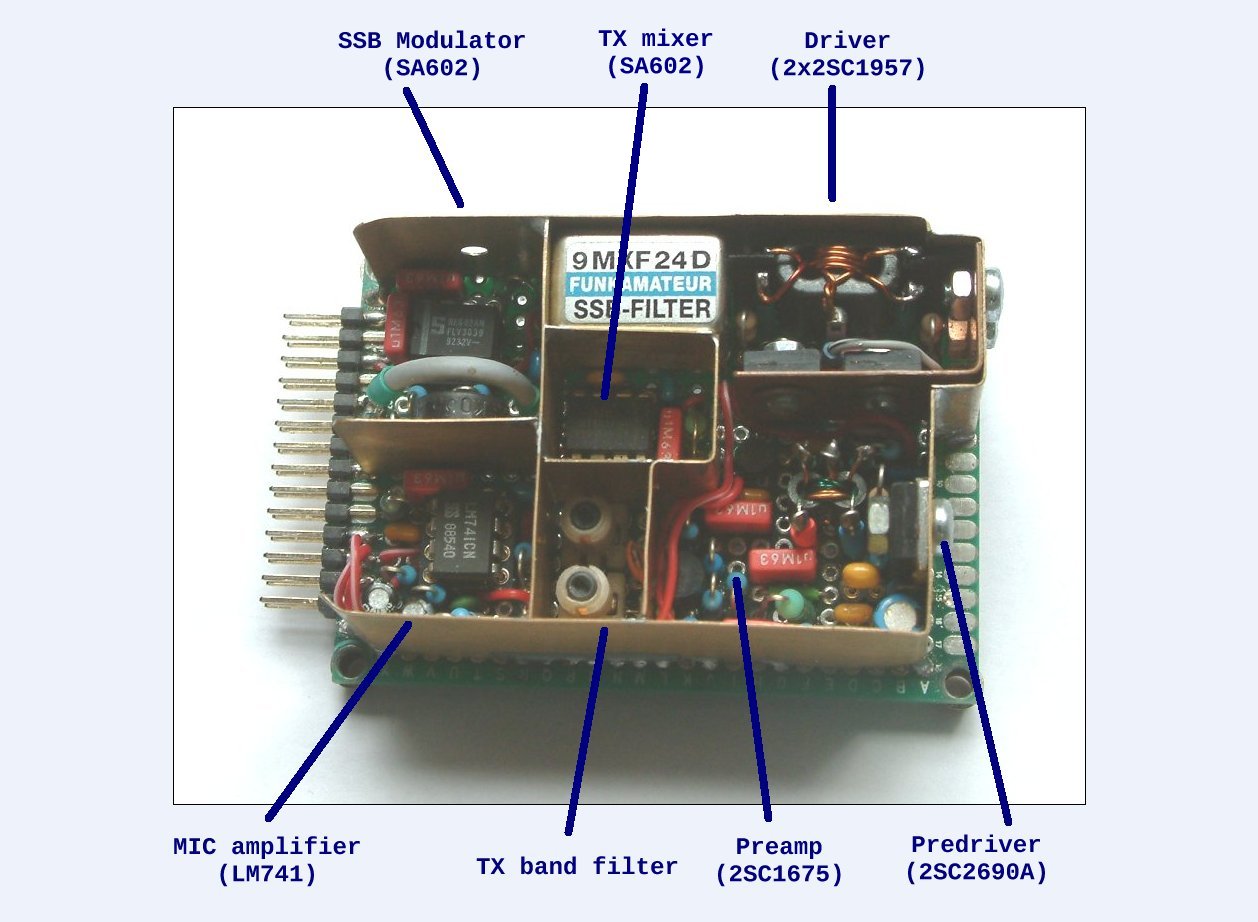
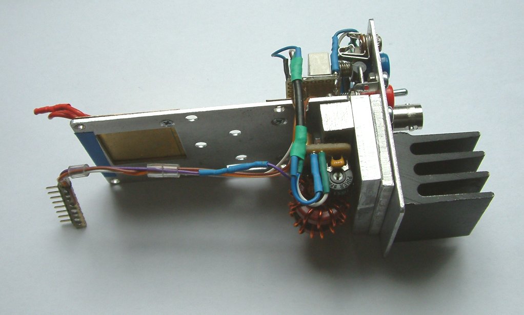
Transmitter board for 40 meter QRO transceiver (by DK7IH)
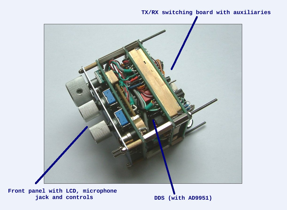
These 3 boards are stacked and plugged into the front unit that you can see underneath. The front subassembly is formed of
- the front panel with user controls, microphone socket and LCD
- the DDS system and
- the relay switching board.
Both construction groups are joined in an angle of 90° by a set of plugs and sockets so that they can be put apart easily and fast for service or improvements. All boards are made of 5×7 cm “FR4” material Veroboards.
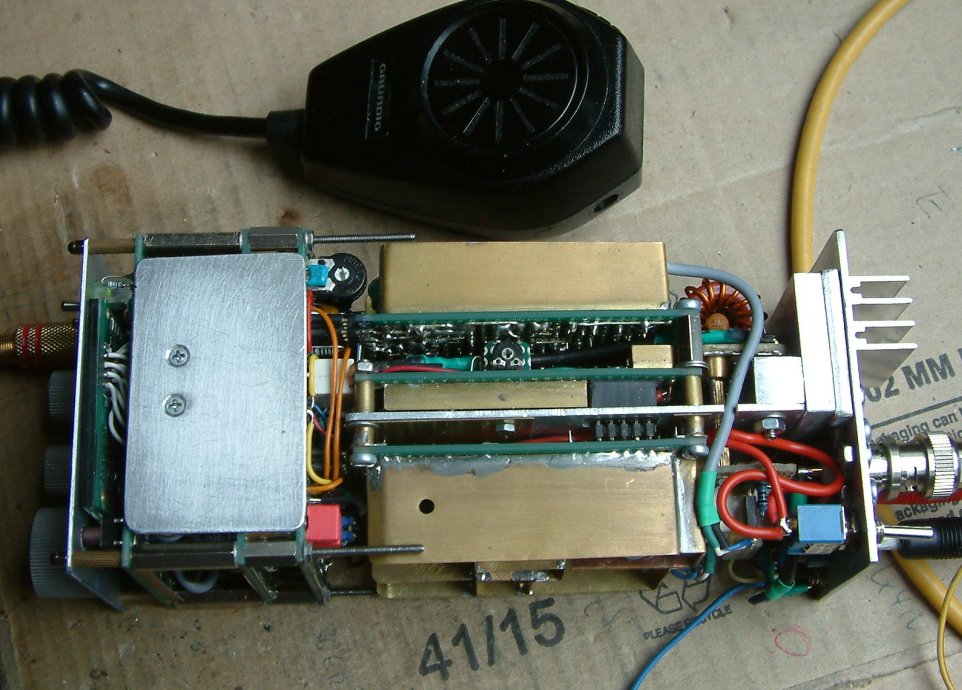
In the center of the right board package you can see the PA amplifer, capable of delivering 50 to 70 watts SSB signal, on top the rx board, at the bottem the transmitter board.
Thermal considerations
An important issue for a high power transceiver is the transmitter’s final amplifier. Particularly thermal conductivity should be kept in mind. In this case one problem, I thought, might occur because the power transistors are not mounted directly to the rear panel of the transceiver where heat can be lead to the outside easily. Here, the two MRF455s are sited in the center of the sandwich construction holding the 3 main rf boards. But as this transceiver is for voice operation only with its comparatively low duty cycle of 10 to 20%, this was not considered as an unsolvable problem. But thermal aspects must be kept in mind, anyway.
Practical solution
As you can see, the final transmitter stage is based on an aluminium sheet metal of 2 mm thickness. Under the board there is a second layer also of 2 millimiter thickness aluminium. By the rear end it is joined to a solid piece of square shaped aluminium rod that itself is connected to another two thick layers of alumium which are srewed to the rear panel holding a heat sink. For this heat sink I’m currently searching a more massive one.
Practical outcomes
The thermal test was a longer QSO with Dave, M5AFD . During this longer QSO with transmission times of up to 3 to 4 minutes each the center alu panel got a temperature of 60° to 65° centigrade. Thermal stress? Not worth mentioning yet!
Current state
So far I’ve done about 50 QSOs on 40 meters with this rig, gradually improving some things. Later I will publish the detailed scheme as soon as it is finished. By now prospects are good to bring this compact QRO transceiver with me on a holiday trip to Jersey Island planned this summer.
Stay tuned! 73 de Peter (DK7IH)
My congrat-s!! I am impressed with a compact size and tidy planning of interconnections.
I am working on a portable multi band rig now – 80..15m bands, around 40W, internal batteries, ATU and built in remote for multi element antenna array direction switching. It is 25*9*15(depth)cm. Yours looks quite smaller.
Thank you for the compliments. Have fun building your multibander! 😉 73 de Peter
Thank you very much! 73 de Peter!
Very goood page !… Very good projects!… Thanks a lot !!!… 73´s
Excellent home brewing… Peter. Congratulations.. being a home brewer I can feel the beauty of your work..I have seen that MRF455 Amplifier circuit in your website and can you provide the values of RF chokes in that circuit. Bias voltage line RFC and Collector voltage line two RFCs..? Do there any negative feed back required? if so the resistor value and capacitor values ? In some circuits I have seen a capacitor across collectors and one from collector to ground also.. Is it required . If so the values also. I want to build one amplifier . I do not get your mail id.. other wise I would have mail you with the request.. Thanks
VU2XTO, Gopan
Hi Gopan,
thanks for your response. Here are some values, they are, in general, not critical: RF chokes: 22uH to 100 uH is OK. There is no neg. feedback because the PA is monoband. Since the PA worked very stable I let it run on full gain without any neg. feedback. If it oscillates I recommend 0.1 uF and starting from 330 Ohms downward until oscillations stop.
73 de Peter (DK7IH)