Recently I thought about how small a fully functionable ham radio could be. Or to say in other words: Should it be possible to build a QRP SSB transcevier that fits into a shirt pocket?
When searching the web for very small amateur radio SSB transceivers I found Pete Juliano’s (N8QW) “Shirt pocket transceiver“. This is a really neat transceiver with 2 Watts of output as Pete says.
My goal was to achieve also 2 Watts of output but keeping the rig even smaller. This was, as I quickly recognized, only possible by replacing conventional through-hole construction by using SMD components to a wide extent. Other things that had to be done were to get an LCD with as little physical expansion as possible and to find small potentiometers for the front panel, also as small as possible.
As an LCD due to the prerequisites mentioned before I use an OLED with 0.96″ diagonal size. This display is available in SPI or I²C/TWI interface technology. Due to the fact that I²C/TWI only uses 2 control lines (which would save me some effort when wiring this) I chose this version. The rest of the transceiver is standard QRP stuff:
- AD9835 as DDS driven by an Arduino Pro Mini board with ATMega328 uC.
- NE602s as SSB generator, TX mixer, RX mixer and product detector
- MC1350 as IF amp
- Dual-Gate-MOSFET as RX preamp
The only one of the usual suspects missing in this project is the LM386 audio amplifier. This has been replaced by a push-pull audio amp with a PNP/NPN pair of bipolar transistors.
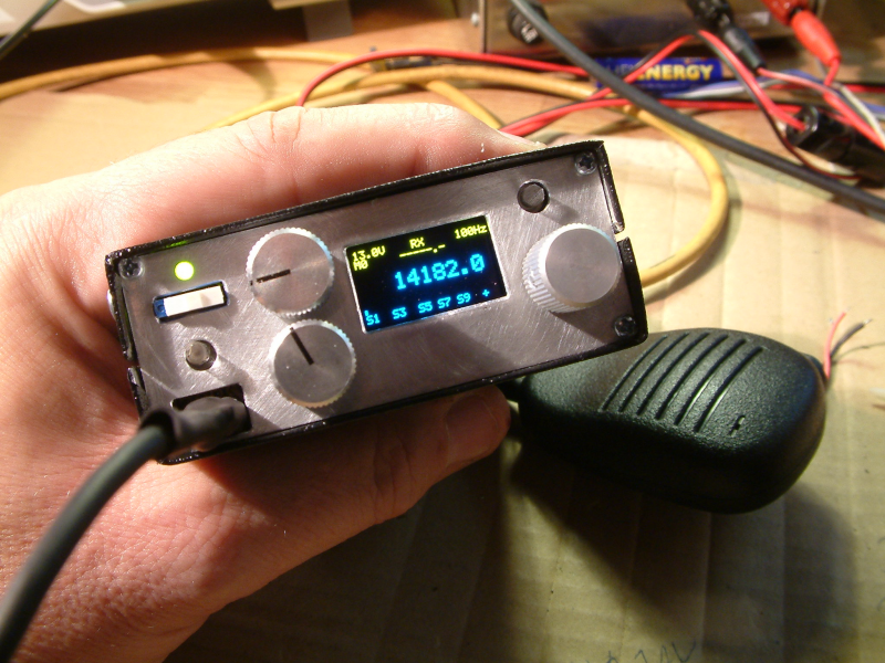
I revived the construction of my 20m-handheld transceiver just to shrink it to a size as small as possible. Underneath you can watch the final state of this project “micro transceiver”. First the outside view. It easily fits, as you can see, in one hand.
Now for the inside:
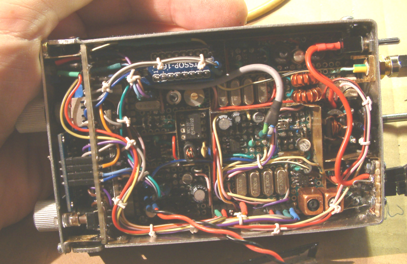
Explanation: Starting in the left upper corner you can see the AD9835 DDS mounted to a breakout board.
Going clockwise next is the receive mixer and the front end with a 40673 dual gate MOSFET transistor. On the right side there is the transmitter. First the final amplifier (push-pull technology), followed by driver and preamp. On the right bottom there is the transmitter’s BPF. Next is the ladder filter for the tx section, “north” of that the transmit mixer, ladderfilter, once again “north” you can see the balanced modulator and the mic amp fed by a shielded cable leading to the front panel.
In the center there is the latter part of the receiver, MC1350 if amp, product detector and audio amps (pre and final stage) sited in the left bottom corner.
The front panel holds the microcontroller (an Arduino Pro mini used as a native AVR without Arduino software), the 0.96″ OLED and the controls.
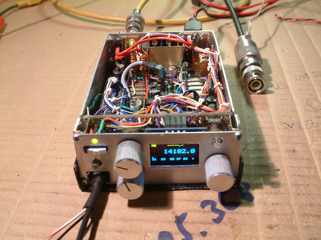
The transceiver interior section viewed from front:
And here is the full circuit of my micro transceiver:
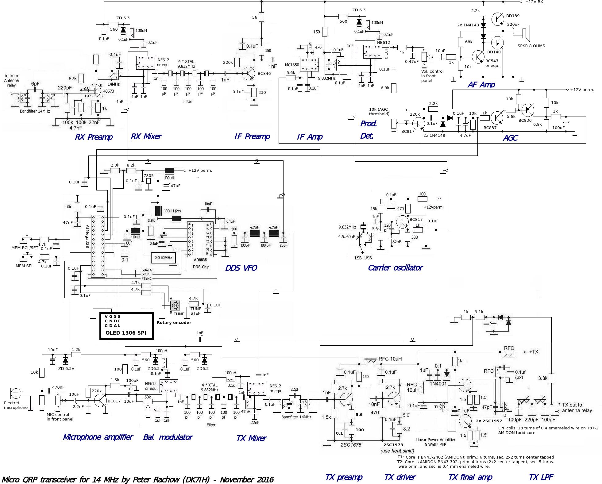
To watch the schematic in full size click here.
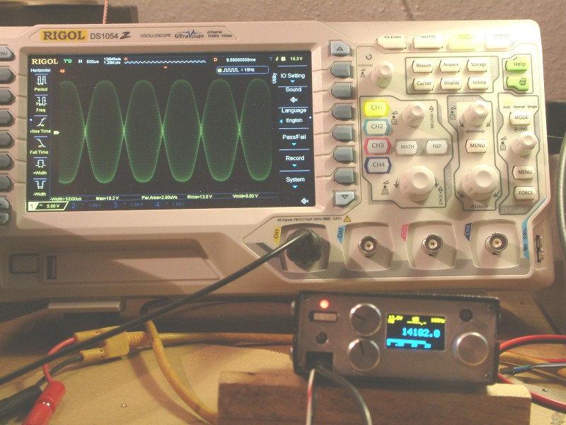
The transmitter puts out 2 to 2.5 watts SSB. Applying a two-tone signal shows the following output:
Excursus: What about using SMDs on Veroboards?
SMDs are not only for printed circuit boards. You can also use them on the standard 2.54mm (0.1″) pitch veroboards.. When you would like to start a similar project, I strongly recommend, in addition to the standard electronic toolcase, the following working material and equipment:
- A high quality temperature stabilized soldering station (I use a Weller WHS 40D) with a 2mm solder tip (wedge-shaped),
- Small pairs of tweezers of various sizes,
- A surgical magnifier (I personally use the “RidoMED” by German manufacturer Eschenbach (Link) which sells for about 320,- Euros)
- 2 or 3 desk lights coming from various angles to you work area.
Where can I get that SMD stuff at a reasonable price?
SMD components are best bought in assortments from the well known electronic warehouses on the web. I bought for example abt. 4000 resistors more than 50 different values) from Chinese vendors via ebay for not more than 5 USD. The same is valid for capacitors. Transistors are also on stock, for example the BC837, BC 846 and other types. ICs in SMD case that can also be purchased are the NE602,612 etc., LM386, MC1350. So, after some weeks a reliable base of SMD componenst is right at hand. For any conceivable QRP project there is enough material available to start.
Soldering SMD components
Standard Veroboards with 0.1″ spacing (2.54mm) can be used with 0603 and 0805 and other SMD parts easily. They well fit into the spaces between the dots on the veroboard.
My method of using SMDs on the veroboard: First put a little bit of solder tin to one of the dots where you want to mount the part. Fix the part with one leg/side by soldering it to the board. Then (if neccessary) readjust the component with the pair of tweezers so that it fits accurately to the board. Keep an eye on the fact that it should be sited plain on the board. If neccessary press it down with a pair of tweezers carefully while heating up the soldering point. Finally check the component from various perspectives!
After having got the correct position of the component, solder the remaining leads and control your work with a magnifying glass, a jeweller’s loupe or the surgical magnifier.
Desoldering SMD components
Desoldering is, to my opinion, easier than with through-hole components:
Parts with 2 soldering areas: Heat the leads of the component from both sides quickly by changing the side with your soldering iron. Soldering tin on both sides must be liquid. Keep the part with the pair of tweezers using your other hand. After some seconds the part will move, in most cases it will stick to the solder tip. Don’t reuse this part! It might have become damaged by thermal stress in case of excessive heat appliance when desoldering process takes longer or by mechanical stress.
Parts with more leads (transistors etc.) : I heat one edge of the part to desolder 2 pins. Simultanously I grap the part with the pair of tweezers and bend the leads up when the solder has melted. Then I desolder the rest of the part.
So, I hope I could give you another inpiration for building a small compact transceiver using SMDs. 73s and thanks for watching!
Peter (DK7IH)
Can you post L/C values for the tuned circuits in your 40meter monoband rig you’ve been posting about for the past few months? Also, how about a link to a larger image for the schematic of this micro rig?
Thanks.
Hello WA2MZE,
the LC coils for 20 meter are 16 turns primary and 4 turns secondary of 0.1 mm diameter. Parallel capacitor is 47 pF on small TOKO style coil former (sample: http://www.electrojumble.org/Toko_425_inside.jpg )
Unfortunately there is no schematic with higher resolution. Due to my mistake I accidentally reduced resolution when finally saving the JPG file. Sorry for that!
73 de Peter
I have browsed my harddrive and found another full size copy of the schematic. Use this link to watch! 73 de Peter
https://radiotransmitter.files.wordpress.com/2016/12/dk7ih-microtransceiver-20-m-2-watts-1.jpeg
Oh, what a beautiful blog! Love it! Keep up the good work Peter. Have a “Guten Rutsch” and a lovely new year! 73 Jan DK3LJ
Thank you very much, dear Jan. Happy New Year also to you! 73 de Peter
Hi Peter, again an outstanding approach you put out here. I have your QRP BAUBUCH in my shack since 1996 and still take it out for reading and studying. I was away from our hobby for abt 20 years due to family and work. Now I am back since 1 year. Many things have changed new stuff is in progress. I also started with some small projects like recievers and Arduino DDS VFOs. Please let me ask you about the sketch you used for you OLED / DDS VFO. Is this sketch available somewhere? I saw the OLED libarie at Tindie. But I could not find the sketch for your DDS VFO incl. the OLED display. Thanks for letting us know.
Hi Stef,
thanks for you comment. Nice to have you back onboard. 🙂 BTW: I have away of hamradio for some years, too, constructing electronical dive computers which was my entry into the world of AVRs. BTW: It’s great to combine computers and radio!
The software for the OLED display I have put into DB3OM’s forum under this link:
http://forum.db3om.de/ftopic25264.html?sid=139b67670772b2848671c1e5d842fff4#p187317
If you can’t access the forum, please drop me a note then I will post it here.
The schemtaic for the OLED/AVR circuit is in the main scheme of the transceiver:
https://radiotransmitter.files.wordpress.com/2016/12/dk7ih-microtransceiver-20-m-2-watts-1.jpeg
Hope, I could help you. And if not, drop me a mail! 😉
73 de Peter
Hi, Peter,
Nice to see your works. I am a retired telecom engineer from India at my 72.
Nice designs in fact using chips like 612 and 1350. I suppose you might have modded the local oscillators using si5351 too for the same “micro Tr/x” and even made a pcb for the same.
I would love to have a set of PCBs from you if a spare and handy. i can pay using paypal or into your a/c.
with your permission I would like to make the Rx section. locally. adopting external si5351based clocks .
congrats and regards
sarma
vu3zmv
Hello Sarma,
thank you very much for your reply on my website. Unfortunately I don’t have PCBs for my designs. This is due to the fact that I only produce a transceiver model one time (just for myself 😉 )and then switch to a new design or topic with the next radio.
Concerning thw Si5351: I recently produced a 40m rig with an Si5351 as VFO and LO but was not 100% satisfied with the noise performance of the chip. I found phase noise slightly too high (compared to AD9xxx DDS chips) but this may be due to to the crystal clock that is on the ADADFRUIT board which I used. But as I don’t have any single Si5351 I have to use the ADADFRUIT breakout board with its possibly negative implications. But I think the Si5351 in general is a good thing for radio homebrewers.
And as all my designs are free for the amateur community you may feel free to use any of them for your own research and/or projects.
vy 73 de Peter (DK7IH)
Hello Peter
What’s the potentiometer values and type?
Hi Kleibe,
I think you are referring to either the mic control (bottom left corner of the schematic) or the AF vol pot (top of picture). Both are 10kOhms linear type. For the AF vol pot it is recommended to use a log type one, but the lin type will fit.
73 de Peter
“Wow, what an incredible project! The Micro QRP Transceiver is truly a marvel of modern engineering. I am in awe of how compact and efficient it is, yet capable of delivering excellent performance. The attention to detail and craftsmanship are evident in every aspect, from the SMT assembly to the design layout. It’s fascinating to see how this pocketful of radio brings so much power and versatility. Thank you for sharing this amazing creation with us! Warm regards, Mabel Chavez.”