Foreword
When I built the semi automatic tuner two years ago I did not take into account some possible shortcomings the device could suffer from. The first of these I noticed when I exceeded power levels of about more or less than 50 watts. In some cases there was rf incoupling leading the microcontroller to fail so that the relay setting was invalid for the given combination of frequency and antenna. The next point was that the algorithm to set the capacitor was far from being optimized. And, as I found out, the maximum inductance I had inlcuded was far too high. On the other hand the lowest indcutance was to big to ensure very fine tuning. So this was revised, too by stepping the inductors more carefully.
The consequence then was a complete reconstruction of the tuner trying to avoid the problems from rf stray energy being coupled into the microcontroller and improving the software and hardware.
Abstract
Thsi article describes a microcontroller driven semi-automatic antenna tuner capable of handling power levels up to 150 watts. The device is a low pass filter tuner manually tuned by setting the optimized L/C combination by hand and then storing the values into the EEPROM of the mictrocontroller to recall them later (seperately for each band from 80 to 10 meters including WARC bands). The tuner ist designed to couple long wire antennas (i. e. longer than half a wavelength) in the frequency range from about 3 MHz to 30 MHz. The antennas can be balanced or non-balanced.
The device uses 7 coils wound on iron powder toroids and a variable capacitor controlled by a motor with a reduction drive and a a device that detects the current turning angle of the rotator.
Also integrated you will find a measurement section to give the current standing wave ratio and put out this on the display.
General layout
The tuner consists of two main parts:
- The microcontroller unit
- The RF unit containing the tuning coils and the variable capacitor.
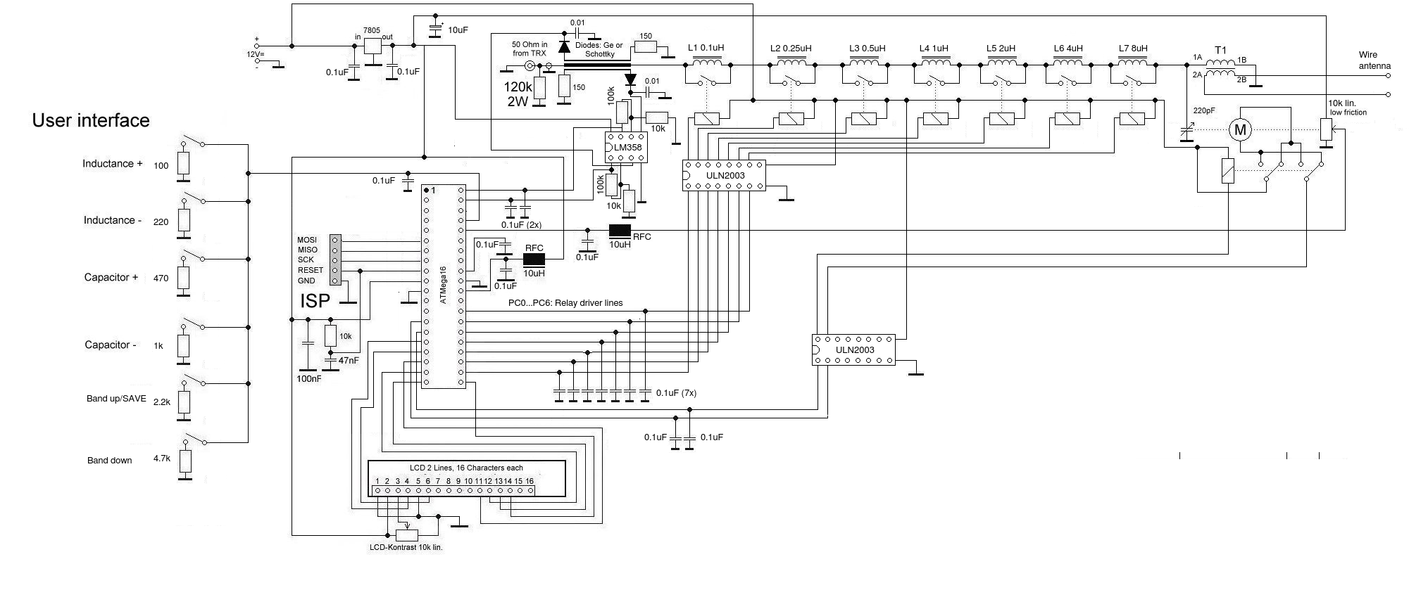
Let’s see the schematic first:

Circuit description
Starting on the left side, you see the microcontroller unit equipped with an 8-bit AVR microcontroller (ATMega16 or similar). The user interface is very simple and made of 6 push buttons. These are connected to GND via switchable individual resistors leading to the ADC3 input of the cntroller. The pull up resistor for ADC3 is activated thus forming a voltage divider and thus an individual ADC value for each push button to be recognized by the software. This is done because it saves control lines and controller ports to a wide extent.
The LCD is a two line 16 characters LCD.
Output ports are connected to ULN2003 driver ICs. These ICs contain a driver capable to handle up to 30V DC including a clamp diode so this IC can drive mtors and relays directly. There are capacitors of 0.1uF connected to the port lines to minimize rf coupling effects.
The RF board is made of 7 coils wound on T68-2 toroids with the inductances given in the schematic:
- L1: 0.1uH: 4 turns,
- L2: 0.25uH: 7 turns,
- L3: 0.5uH: 9 turns,
- L4: 1uH: 13 turns,
- L5: 2uH: 19 turns,
- L6: 4uH: 26 turns,
- L7: 8uH: 37 turns.
Wire gauge is 0.4mm. The inductors are shortened by a 12V relay each if neccessary. So you can (by binary calculation) set any value from 0.1 uH to close to 16uH.
An output transformer is used to give a balanced out for e. g. doublet antenns. It is 10 turns bifilar on a 2.5 cm toroid ferrite core of No. 43 material. If you use a non-balanced antenna you can leave out this transformer.
The capacitor in my construction is a 200pF max. butterfly capacitor with air as dielectric. The advantage of a butterfly type is that it needs only 90° angle to turn it from minimum to maximum capacity. The motor (a 5V dc version) is connected via a 240:1 gear drive by TAMIYA. The motor is pulse driven so it can be directly connected to 12 Volts with running danger to damage it.
The drive has two outlets providing one axle at each side of the drive. To one of the axles I connected the capacitor, the other one connects to a potentiometer to report the current swing angle to the microcontroller. This allows precise feedback of the capacitor’s current position which is essential for setting it to the desired value. The value of this variable resistor does not really matter since it is only a simple voltage divider. Anything between 1k and 10k should fit. Make sure that you use a piece that is easy to turn to minimize friction. To connect the axles I used PVC tubing with an inside diameter of 3 mm.
Also included is a measurement section to give the user a current reading of VSWR. The coupler can be anything you should regard as proper. I used a strip power coupler from an old CB radio. But other systems should also work.
To compensate losses when tuning low frequencies I added a DC amplifier based on an operational dual system amplifier (LM358). There is no means to reduce sensitivity. This is done by regulating the input power of the driving transmitter. The software will give you a readout for FWD and REF power in the range from 0 to 999. Tune to maxmimun FWD and minimum REF energy and everything will be alright! 😉
Practical aspects
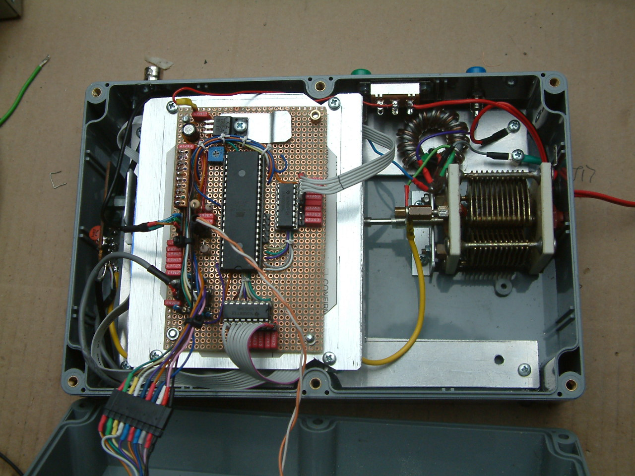
To minimize RF couping into the microcontroller I seperated the control board from the RF board by putting it on a seperate veroboard with an aluminium shielding underneath:

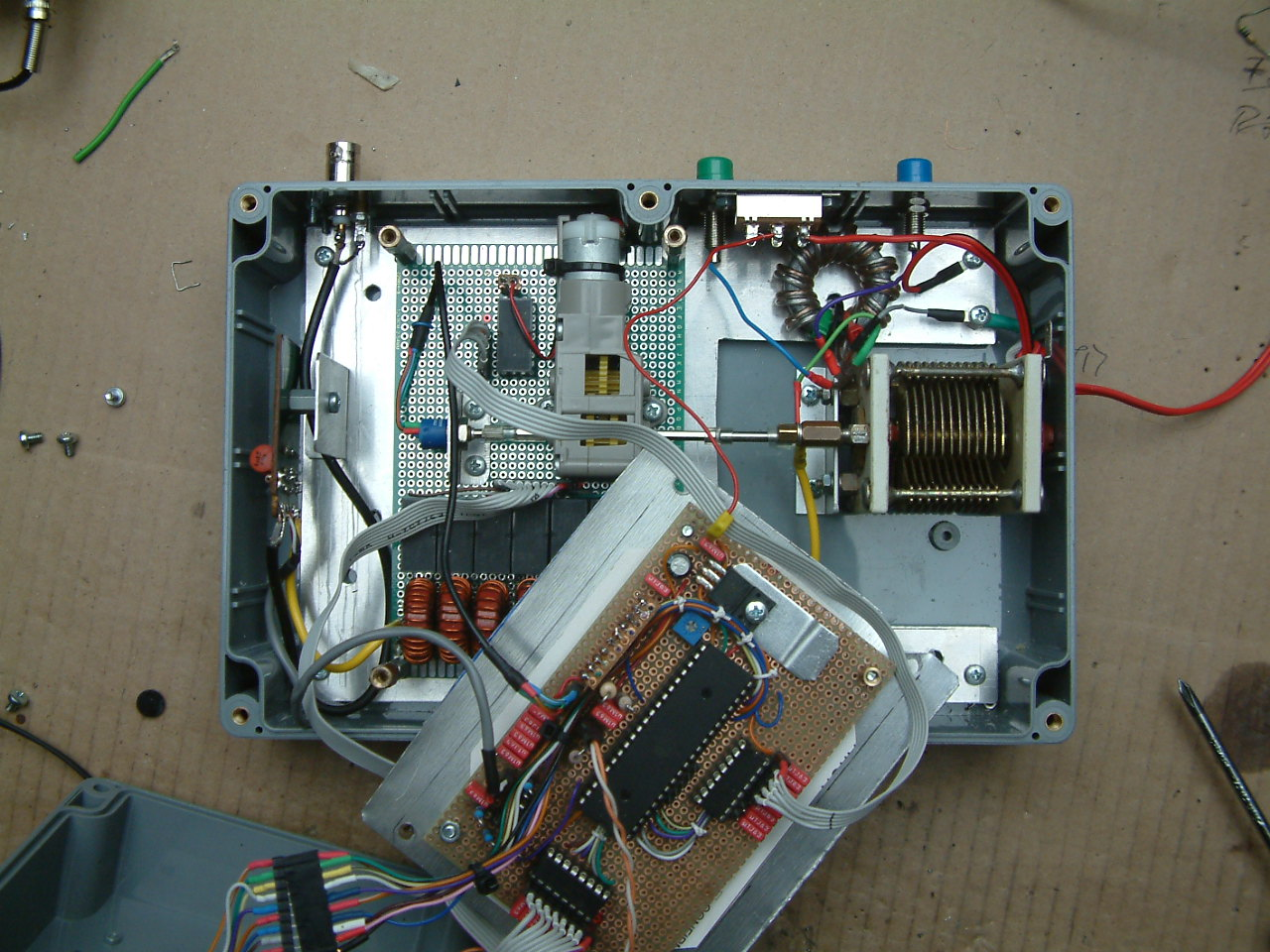
The RF board is mounted to the bottom of the case, here with dismantled controller board. The controller board is sited on top of the package.

On the right side there is the variable butterfly capacitor, on the board, centered you can see the motor plus the reduction drive. On the left side of this there is a small potentiometer that forms the turning angele detector. To connect this to the ADC of the controller it is highly recommended to use shielded cable!
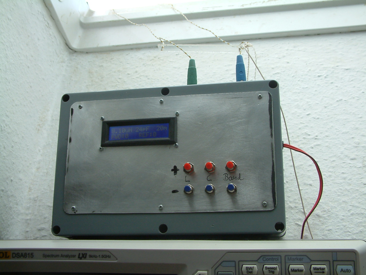
To come to an end, here is the deveice positioned under the roof window of my shack directly connected to the ladder line:

Thanks for reading and enjoy your radio! 73 de Peter (DK7IH)
The software
(Apology for having some comments in German. I have been using this code for centuries! 😉
/*****************************************************************/
/*              Antennatuner with ATMega 16 V2                   */
/*  ************************************************************ */
/*  Microcontroller:  ATMEL AVR ATmega16, 8 MHz                  */
/*                                                               */
/*  Compiler:         GCC (GNU AVR C-Compiler)                   */
/*  Author:           Peter Rachow DK7IH                         */
/*  Last cahnge:      2018-07-27                                 */
/*****************************************************************/

/*    PORTS */
// O U T P U T
// LCD
// RS      = PD2
// E       = PD3
// D4...D7 = PD4..PD7

//Coil relays: PC0...PC6
//Motor drive on/off: PD1
//Motor direction relay: PD0
//Extra capacitor 200pF: PC7 (not yet!)

//I N P U T
//ADC0: SWR-Meter 0
//ADC1: SWR-Meter 1
//ADC2:
//ADC3: Keys
//ADC4: Potentiometer for Capacitor position

#include <inttypes.h>
#include <stdio.h>
#include <stdlib.h>
#include <math.h>

#include <avr/io.h>
#include <avr/interrupt.h>
#include <avr/sleep.h>
#include <avr/eeprom.h>
#include <util/delay.h>

int main(void);

#define LCD_INST 0x00
#define LCD_DATA 0x01

#define MAXCAP 220
#define CAPDELAY 10
#define MAXBANDS 7

void lcd_write(char, unsigned char);
void set_rs(char);
void set_e(char);
void lcd_init(void);
void lcd_cls(void);
void lcd_line_cls(int);
void lcd_putchar(int, int, unsigned char);
void lcd_putstring(int, int, char*);
int lcd_putnumber(int, int, long, int);
void lcd_display_test(void);

//BAND DISPLAY & MISC
void show_band(int);
void show_meter(int, int, int);
void define_chars(void);

//Coils & Cpas
void set_coils(int);
void set_cap(int);
void rotate_cap(int);
int get_cap(void);

//ADC
int get_adc(int);
int get_keys(void);

//Delay
void wait_ms(int);

//String
int int2str(long, int, char *, int);
int stringlen(char *);


long runsecs = 0;

/**************************************/
/* Funktionen und Prozeduren fuer LCD */
/**************************************/
// LCD
// RS      = PD2
// E       = PD3
// D4...D7 = PD4..PD7

/* Ein Byte (Befehl bzw. Zeichen) zum Display senden */
void lcd_write(char lcdmode, unsigned char value)
{
    int x = 16, t1;

    set_e(0);

    if(!lcdmode)
	{
        set_rs(0);    //RS=0 => INST
	}
    else
	{
        set_rs(1);    // RS=1 => DATA
	}

    wait_ms(4);

    //Hi nibble
    set_e(1);
	for(t1 = 0; t1 < 4; t1++)
	{
	    if(value & x)
	    {
	       PORTD |= x;
	    }
        else
	    {
           PORTD &= ~(x);
	    }

		x <<= 1;
	}
	set_e(0);

	x = 16;

	// Lo nibble
	set_e(1);
	for(t1 = 0; t1 < 4; t1++)
	{
	    if((value & 0x0F) * 16 & x)
	    {
	       PORTD |= x;
	    }
        else
	    {
           PORTD &= ~(x);
	    }

		x <<= 1;
	}
    set_e(0);

}

//RS
void set_rs(char status) //PD2
{
    if(status)
	{
        PORTD |= 4;
	}
    else
	{
	    PORTD &= ~(4);
	}
}

//E
void set_e(char status)  //PD3
{
    if(status)
	{
        PORTD |= 8;
	}
    else
	{
	    PORTD &= ~(8);
	}
}

/* Ein Zeichen (Char) zum Display senden, dieses in */
/* Zeile row und Spalte col positionieren           */
void lcd_putchar(int row, int col, unsigned char ch)
{
    lcd_write(LCD_INST, col + 128 + row * 0x40);
    lcd_write(LCD_DATA, ch);
}


/* Eine Zeichenkette direkt in das LCD schreiben */
/* Parameter: Startposition, Zeile und Pointer   */
void lcd_putstring(int row, int col, char *s)
{
    unsigned char t1;

    for(t1 = col; *(s); t1++)
	{
        lcd_putchar(row, t1, *(s++));
	}
}


/* Display loeschen */
void lcd_cls(void)
{
    lcd_write(LCD_INST, 1);
}


/* LCD-Display initialisieren */
void lcd_init(void)
{
    /* Grundeinstellungen: 2 Zeilen, 5x7 Matrix, 4 Bit */
    lcd_write(LCD_INST, 40);
    lcd_write(LCD_INST, 40);
    lcd_write(LCD_INST, 40);

    //MAtrix 5*7
    lcd_write(LCD_INST, 8);

    /* Display on, Cursor off, Blink off */
    lcd_write(LCD_INST, 12);

    /* Entrymode !cursoincrease + !displayshifted */
    lcd_write(LCD_INST, 4);

	//4-Bit-Mode
    lcd_write(LCD_INST, 2);

	lcd_cls();
}


//Write number with given amount on digits to LCD
int lcd_putnumber(int col, int row, long num, int dec)
{
    char *numstr = malloc(32);
    int l = 0;
    if(numstr != NULL)
    {
        int2str(num, dec, numstr, 16);
        lcd_putstring(col, row, numstr);
        l = stringlen(numstr);
        free(numstr);
        return l;

    }
    return 0;
}


void lcd_line_cls(int ln)
{
    int t1;

	for(t1 = 0; t1 < 15; t1++)
	{
	    lcd_putchar(ln, t1, 32);
	}
}
/*****************************************/
//           STRING FUNCTIONS
/*****************************************/
//INT 2 ASC
int int2str(long num, int dec, char *buf, int buflen)
{
    int i, c, xp = 0, neg = 0;
    long n, dd = 1E09;

    if(!num)
	{
	    *buf++ = '0';
		*buf = 0;
		return 1;
	}

    if(num < 0)
    {
     	neg = 1;
	    n = num * -1;
    }
    else
    {
	    n = num;
    }

    //Fill buffer with \0
    for(i = 0; i < 12; i++)
    {
	    *(buf + i) = 0;
    }

    c = 9; //Max. number of displayable digits
    while(dd)
    {
	    i = n / dd;
	    n = n - i * dd;

	    *(buf + 9 - c + xp) = i + 48;
	    dd /= 10;
	    if(c == dec && dec)
	    {
	        *(buf + 9 - c + ++xp) = '.';
	    }
	    c--;
    }

    //Search for 1st char different from '0'
    i = 0;
    while(*(buf + i) == 48)
    {
	    *(buf + i++) = 32;
    }

    //Add minus-sign if neccessary
    if(neg)
    {
	    *(buf + --i) = '-';
    }

    //Eleminate leading spaces
    c = 0;
    while(*(buf + i))
    {
	    *(buf + c++) = *(buf + i++);
    }
    *(buf + c) = 0;

	return c;
}

//STRLEN
int stringlen(char *s)
{
   int t1 = 0;

   while(*(s + t1++));

   return (t1 - 1);
}


//BAND DISPLAY
void show_band(int b)
{

    char *band_str[] = {"80m", "40m", "30m", "20m", "17m", "15m", "12m", "10m"};
    lcd_putstring(0, 13, band_str[b]);
}

//Meter (max. value = 25)
void show_meter(int value, int value_old, int pos)
{
	#define MAXBLOCKS 4
    int v1, v2, v3, i1;

    //Clear meter (5 chars) if new value > old value
    if(value < value_old)
    {
        for(i1 = 0; i1 < MAXBLOCKS; i1++)
        {
	        lcd_putchar(1, i1 + pos * 6, 32);
        }
	}

	v1 = (int) value / MAXBLOCKS; //Full blocks, 5 cols each
    v2 = value - v1 * MAXBLOCKS;  //Rest
	if(v1 > MAXBLOCKS)
	{
		v1 = MAXBLOCKS;
	}

	if(value >= value_old)
	{
	    v3 = (int) value_old / MAXBLOCKS; //Full blocks, 5 cols each, already drawn
	}
	else
	{
		v3 = 0;
	}

	//Full blocks
	for(i1 = v3; i1 < v1; i1++)
	{
	    lcd_putchar(1, i1 + pos * 6, 4);
	}

	//Rest
	if(i1 < MAXBLOCKS)
	{
		if(v2)
	    {
	        lcd_putchar(1, i1 + pos * 6, v2 - 1);
	    }
        else
        {
            lcd_putchar(1, i1 + pos * 6, ' ');
        }
	}
}

//PROGRAM CUNSTOM CHARS FOR S-SMETER
void define_chars(void)
{
    int i1;
	unsigned char adr = 64;

	unsigned char b1[] = {0x00, 0x00, 0x10, 0x10, 0x10, 0x10, 0x00, 0x00, //S-Meter blocks
	                      0x00, 0x00, 0x18, 0x18, 0x18, 0x18, 0x00, 0x00,
						  0x00, 0x00, 0x1C, 0x1C, 0x1C, 0x1C, 0x00, 0x00,
						  0x00, 0x00, 0x1E, 0x1E, 0x1E, 0x1E, 0x00, 0x00,
						  0x00, 0x00, 0x1F, 0x1F, 0x1F, 0x1F, 0x00, 0x00,
						  	0x0,0x0,0x4,0xe,0x4,0x0,0x0, 0, //+
						  	0x4,0xe,0x4,0x0,0x4,0xe,0x4,0, //++
						  0x00, 0x01, 0x02, 0x12, 0x0A, 0x04, 0x00, 0x00  //Tick

						  };
	//Dummy operation!
	lcd_write(LCD_INST, 0);
	lcd_write(LCD_DATA, 0);

    //Load data into CGRAM
	for(i1 = 0; i1 < 64; i1++)
	{
	    lcd_write(LCD_INST, adr++);
		lcd_write(LCD_DATA, b1[i1]);
	}
}


/////////////////////////////////////
//
// C O I L S & C A P S
//
/////////////////////////////////////
void set_coils(int pattern)
{
    int unsigned t1, x = 1, p = pattern;

    //Inductance in uH  * 100
    int i0[] = {10, 25, 50, 100, 200, 400, 800}, i1 = 0;

    //lcd_putstring(0, 10, "    ");
    //lcd_putnumber(0, 10, p, -1, -1, 'l', 0);

    for(t1 = 0; t1 < 7; t1++)
    {
		if(p & x)
        {
            PORTC &= ~(x);
            i1 += i0[t1];
        }
        else
        {
            PORTC |= x;
        }
        x <<= 1;
     }
     lcd_putstring(0, 0, "       ");
     lcd_putstring(0, lcd_putnumber(0, 0, i1, 2), "uH");
}

void set_cap(int cap)
{

    if(cap < 0 ||cap > MAXCAP)
    {
		return;
	}

	lcd_putstring(0, lcd_putnumber(0, 7, cap, -1) + 7, "pF");
	wait_ms(500);
	/*
    lcd_putnumber(0, 0, get_adc(4), -1, -1, 'l', 0);
    lcd_putnumber(0, 8, cap, -1, -1, 'l', 0);
    lcd_putnumber(1, 0, (int) adc0, -1, -1, 'l', 0);
    */

    while(get_cap() > cap)
    {
		rotate_cap(0);
		lcd_putstring(0, 7, "      ");
        lcd_putstring(0, lcd_putnumber(0, 7, get_cap(), -1) + 7, "pF");
        if(get_keys() == 5 || get_keys() == 6) //Quit if band QSY key is pressed
        {
			return;
		}
    }

    while(get_cap() < cap)
    {
		rotate_cap(1);
		lcd_putstring(0, 7, "      ");
        lcd_putstring(0, lcd_putnumber(0, 7, get_cap(), -1) + 7, "pF");
        if(get_keys() == 5 || get_keys() == 6) //Quit if band QSY key is pressed
        {
			return;
		}
    }


}

//Measure real cap val from sensor
int get_cap(void)
{
	double val = (double) (get_adc(4) - 384) * MAXCAP / 256;

	return (int) val;
}

void rotate_cap(int direction)
{
	if(direction)
	{
		PORTD &= ~(1); //RelayOFF
	}
	else
	{
	    PORTD |= 1;   //Relay ON
	}

	PORTD |= 2;   //Motor ON
	wait_ms(CAPDELAY);
	PORTD &= ~(2);  //Motor OFF
	wait_ms(CAPDELAY);
}


ISR(TIMER1_OVF_vect)   	   // Timer1 Überlauf
{
    runsecs++;
    TCNT1 = 57724;
}

//***************************************************
//                      ADC
//***************************************************

int get_adc(int adcmode)
{
    int adc_val = 0;


	ADMUX = (ADMUX &~(0x1F)) | (adcmode & 0x1F);     // Kanal adcmode aktivieren PA0=TUNE
    wait_ms(3);

    ADCSRA |= (1<<ADSC);
	wait_ms(3);

	adc_val = ADCL;
    adc_val += ADCH * 256;

	while(ADCSRA & (1<<ADSC));

	return adc_val;
}

//Read keys via ADC0
int get_keys(void)
{

    int key_value[] = {18, 22, 29, 43, 74, 132};

    int t1;
    int adcval = get_adc(3);

    //TEST display of ADC value
    /*
    lcd_cls();
    lcd_putnumber(0, 0, get_adc(3), -1, -1, 'l', 0);
    return 0;
    */

    for(t1 = 0; t1 < 6; t1++)
    {
        if(adcval > key_value[t1] - 2 && adcval < key_value[t1] + 2)
        {
			 return t1 + 1;
        }
    }

    return 0;
}

/***************************************************/
/* Wartezeit in Millisekunden bei fck = 8.000 MHz  */
/***************************************************/
void wait_ms(int ms)
{
  int t1, t2;

  for(t1 = 0; t1 < ms; t1++)
    for(t2 = 0; t2 < 137 * 8; t2++)
      asm volatile ("nop" ::);
}

int main()
{
	int t1;
	int key;     //Keystroke
	int adc_val; //Value of ADC
    int i = 65;  //L
    int band = 0;
    int l1 = 0, c1 = 0;

    //Standard values for DK7IH antenna
    //L=      - (128), 8uH(64), 4uH(32), 2uH(16), 1uH(8), 0.5uH(4), 0.25uH(2), 0.125uH(1)
    int std_l [] = {65, 33, 12, 8, 6, 4, 3, 2, 1};
    int std_c [] = {172, 41, 75, 110, 88, 55, 33, 17};

    //Meter data
    int s0, s1;
    int s0_old = -1, s1_old = -1;
    int s0off, s1off;
    int loopcnt0 = 0;;

    int ok = 0;
    long runsecs2 = 0;

	/* Set ports */
    /* OUTPUT */
    DDRB = 0x1F; //Relays 1.55 of cap switching
    DDRC = 0x7F; //Relays for coils
    DDRD = 0xFF; //LCD data on PD4...PD7
                 //LCD RS:PD2, E:PD3
                 //PD0, PD1: Relay 6 and 7 of cap switches

    PORTA = 0x08; //Pullup resistor for keys' input

    //Display
    lcd_init();
	wait_ms(500);
	lcd_cls();
	lcd_putstring(0, 0, " DK7IH Antenna");
	lcd_putstring(1, 0, " Tuner Ver. 2.0");
	wait_ms(500);
	lcd_cls();

	//Watchdog abschalten
	WDTCR = 0;
	WDTCR = 0;

	//ADC initialisieren
    ADMUX = (1<<REFS0);     // Referenz = AVCC
    ADCSRA = (1<<ADPS2) | (1<<ADPS1) | (1<<ADEN); //Frequenzvorteiler 64 u. //ADC einschalten
	ADCSRA |= (1<<ADSC); //Eine Wandlung vornehmen
	while (ADCSRA & (1<<ADSC)); //Eine Wandlung abwarten
    adc_val = ADCL;
    adc_val += ADCH * 256;   //Wert auslesen
	adc_val = 0;

	//Timer 1
	TCCR1A = 0;                      // normal mode, keine PWM Ausgänge
    TCCR1B = (1<<CS12) + (1<<CS10) ;   // start Timer mit Systemtakt, Prescaler = /1024
	                                    //Auslösung des Overflow alle Sekunde sec.
    TIMSK = (1<<TOIE1);   // overflow aktivieren.
	TCNT1 = 57724;        //Startwert für Sekundentakt

    //Define custom chars for meter
    //define_chars();

    //Load standard data if eeprom cell empty
    for(t1 = 0; t1 < 8; t1++)
    {
		if(eeprom_read_byte((uint8_t*)(t1 * 2)) == 255)
		{
			eeprom_write_byte((uint8_t*)(t1 * 2), std_l[t1]);
			eeprom_write_byte((uint8_t*)(t1 * 2 + 1), std_c[t1]);
		}
	}


    //Get recent data
   	band = eeprom_read_byte((uint8_t*)32);
   	if(band < 0 || band > MAXBANDS)
	{
	    band = 3;
	}
	show_band(band);

	l1 = eeprom_read_byte((uint8_t*)(band * 2));
	if(l1 >= 0 && l1 < 128)
	{
		set_coils(l1);
	}
	else
	{
		set_coils(65);
		lcd_line_cls(1);
		lcd_putstring(0, 0, " -x-uH");
		wait_ms(1000);
	}
	c1 = eeprom_read_byte((uint8_t*)(band * 2) + 1);
	if(c1 >= 0 && c1 < MAXCAP)
	{
		set_cap(c1);
	}
	else
	{
		set_cap(110);
		lcd_line_cls(1);
		lcd_putstring(0, 0, " -x-pF");
		wait_ms(1000);
	}
    sei();

    show_band(band);

    //Calculate 0-offset of swr meter
    s0off = get_adc(0);
    s1off = get_adc(1);

    for(;;)
	{
		key = get_keys();
		if(i > 0 && key == 2)
		{
			i--;
		    set_coils(i);
		    wait_ms(50);
		}

		if(i < 127 && key == 1)
		{
			i++;
		    set_coils(i);
		    wait_ms(50);
		}

		while(get_cap() > 0 && key == 4) //C(-)
		{
			rotate_cap(0);
		    lcd_putstring(0, 7, "      ");
            lcd_putstring(0, lcd_putnumber(0, 7, get_cap(), -1) + 7, "pF");
            wait_ms(100);
            key = get_keys();
		}

		while(get_cap() < MAXCAP && key == 3) //C(+)
		{
			rotate_cap(1);
		    lcd_putstring(0, 7, "      ");
            lcd_putstring(0, lcd_putnumber(0, 7, get_cap(), -1) + 7, "pF");
            wait_ms(100);
            key = get_keys();
		}

        if(band > 0 && key == 6)         //Band (-)
        {
			band--;

			while(!eeprom_is_ready());
		    eeprom_write_byte((uint8_t*)32, band);

			lcd_putstring(1, 0, "Recalling.");

			l1 = eeprom_read_byte((uint8_t*)(band * 2));
			c1 = eeprom_read_byte((uint8_t*)(band * 2 + 1));

	        if(l1 >= 0 && l1 < 128)
	        {
		        set_coils(l1);
		        i = l1;
	        }
	        else
	        {
		        set_coils(65);
		        lcd_putstring(0, 0, " -x-uH");
		    }


			if(c1 >= 0 && c1 <= MAXCAP)
			{
			    set_cap(c1);
			}
			else
			{
				lcd_putstring(0, 7, "-x-pF");
			}

			show_band(band);
			lcd_putstring(1, 0, "             ");
			while(get_keys());
		}


        if(key == 5) //Band (+)
		{
		    show_band(band);
			lcd_line_cls(1);

		    runsecs2 = runsecs;
			ok = 0;
			lcd_putstring(1, 0, "Waiting....");
			while(get_keys() == 5 && !ok)
			{

			    lcd_putnumber(1, 10, 3 - (runsecs - runsecs2), -1);
				if(runsecs - runsecs2 > 2)
				{
				    ok = 1;
				}
			}

			if(runsecs > runsecs2 + 1) //Key has been pressed for longer than a second, new values for current band to be set
			{                          //Also store values in EEPROM
			    while(!eeprom_is_ready());
				eeprom_write_byte((uint8_t*)(band * 2), i);

			    while(!eeprom_is_ready());
				eeprom_write_byte((uint8_t*)(band * 2 + 1), get_cap());

				while(!eeprom_is_ready());
				eeprom_write_byte((uint8_t*)32, band);

	            lcd_line_cls(1);
				lcd_putstring(1, 0, "Stored.");
				wait_ms(1000);
				lcd_line_cls(1);
			}
            else
			{
			    if(band < MAXBANDS) //Change band 1 up
				{
				    band++;
				}

				while(!eeprom_is_ready());
				eeprom_write_byte((uint8_t*)32, band);

				show_band(band);

				lcd_putstring(1, 0, "Recalling.");

			    l1 = eeprom_read_byte((uint8_t*)(band * 2));
				c1 = eeprom_read_byte((uint8_t*)(band * 2 + 1));

	            if(l1 >= 0 && l1 < 128)
	            {
		            set_coils(l1);
		            i = l1;
	            }
	            else
	            {
		            set_coils(65);
		            lcd_putstring(0, 0, " -x-uH");
		            wait_ms(1000);
		        }


			    if(c1 >= 0 && c1 <= MAXCAP)
			    {
			        set_cap(c1);
			    }
			    else
			    {
				     lcd_putstring(0, 7, "-x-pF");
			    }
			    lcd_putstring(1, 0, "             ");
			}
		}

		//Meter check
        if(loopcnt0++ > 10)
        {

            s0 = get_adc(0) - s0off;
            s1 = get_adc(1) - s1off;

            if(s0 != s0_old)
            {
				if(s0 > 999)
				{
					s0 = 999;
				}
				lcd_putstring(1, 0, "FWD:    ");
				lcd_putnumber(1, 4, s0, -1);
				s0_old = s0;
			}

			if(s1 != s1_old)
            {
				if(s1 > 999)
				{
					s1 = 999;
				}
				lcd_putstring(1, 8, "REF:     ");
				lcd_putnumber(1, 12, s1, -1);
				s1_old = s1;
			}

            loopcnt0 = 0;
        }

	}
	return 0;
}