Preface
Currently I am revising older projects that are in my radio shelf, some of them not finished yet, pageponed to a later date, some without a cabinet, some with severe problems with performance and so on. All the stuff that needs a “second chance” ;-). This project is one of this collection. The transmitter did not work correctly (severe parasetic oscillations occurred when the section was driven to power levels >1 watt).
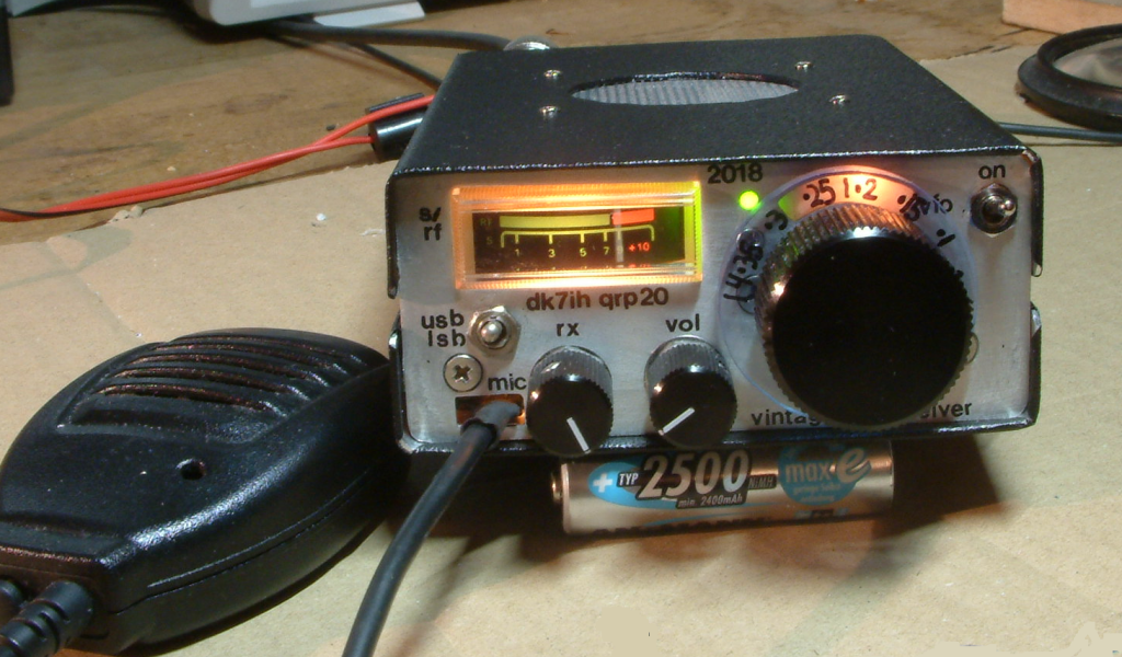
By careful testing and examining I found the reason: The grounding of the rf power amplifier stage was defective due to a connection that had not been soldered properly. After having cured that I found the output was 5 to 6 watts PEP output (very clean). Then, having the project on “GO!”, I finished the design. Thus I got a nice little “vintage style” SSB QRP trsanceiver as a travel or hiking companion:
Basic concept
Frequent readers on my blog know that one thing I really enjoy is building radios based on a minimalist concept. The fewer components you need for a working transceiver, the better it is. At least in my point of view. Here is another one of these “very lean design” transceivers.
The radio originally was designed as a study for my “Old School Transceiver“. After having not built a “real” analog VFO for a number of years I wanted to find out if I still can set up a construction that is really stable concerning frequency. And because it is not very challenging to just watch the result on a frequency counter, a full transceiver had to be built along with the VFO. The VFO was OK, (see later text!) the power transmitter, as mentioned before, was not. Until I had revised it.
The design is another remake of the „Kajman Transceiver“ by SQ7JHM. A design I absolutely love because of its simplicity. The radio basically has been designed for 80 meters (even when lot of websites quote it as a 20m rig) so it shows some weaknesses when adapted to 14MHz without any changes. Thus some improvements had to be made.
Improving performance of the SQ7JHM basic design
Some changes that were top of the agenda to meet my requirements:
- The receiver needed a preamplifier for bands where atmospheric noise is not that strong. A dual-gate MOSFET equipped radio frequency preamplifier improves noise figure significantly and can be put into the AGC chain to give more dynamic range and a more pleasant listening experience.
- An AGC (automatic gain control) is a good idea if you want to use the receiver in a more comfortable way without the need to lower the volume when strong stations appear. In addition the S-meter reading can be derived from the output of the AGC DC amplifier stage.
- A little bit more rf output power can be achieved by using a push-pull amplifier. Linearity also improves to a certain degree when using this design because AB mode combined with separated amplification of the half waves plus suppression of even-order harmonics.
- To enhance receiver gain a single stage interfrequency amplifier has been added that is only in use when on receive. It is also connected to the AGC chain.
- And, last, a microphone amplifier allows you to talk in a moderate way into the microphone which is good for me because I often have my QSOs when the rest of the family is asleep and not keen on listening to my strange “This is DK7IH/QRP, do you copy?” messages.
The schematic of my enhanced design:
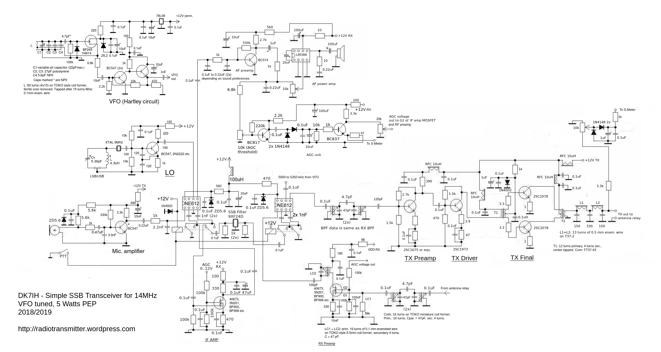
Fascination originates from the fact that you only need a handful of components (OK your hand should not have the size of that of a new born baby!) to set up a working short wave SSB transceiver.
The VFO
Some thoughts on frequency stability
Careful design is the key for stable operation. This means component selection as well as setting it up on the veroboard.
The basic problem for every conventional free running VFO is temperature and its influence on the size of components. Due to the theory of thermodynamics all materials change their mechanical dimensions with temperature. This is caused by the kinetic energy of the molecules forming the crystals of a solid body. Thermal energy leads to enhanced oscillation of the molecules and therefore the need of larger spaces of each in individual molecule in a crystal. Because we have capacitors in a tuned circuit this will affect the values of all caps (wanted and unwanted ones) to a certain degree.
Something that helps the builder is called “temperature coefficient”. This means that electronic components increase OR decrease their respective value when they get warmer. The first is called “positive temperature coefficient”, the opposite is called “negative temperature coefficient”. So, you might guess, the fine art of radio building involves the knowledge of the characteristic behavior of components when heated.
I quote my findings about temperature behavior listed in the article referred to on the beginning of this text:
Capacitors:
- Ceramic capacitors: —
- Polystyrene capacitor: –
- NP0 (C0G) capacitor: no measurable effect
Inductors:
- Air coil on polystyrene coil former: +++
- Coil wound on T50-6 yellow toroid: +
The more “+” or “-” signs, the more steep the function of T->dC or T->dL is. So you can see: The best choice are polystyrene capacitors combined with coil on a yellow toroid. This combination is likely to outbalance temperature effects. If extra capacity is needed, NP0 caps are recommended.
The circuit
From the existing principles of building a free running radio frequency oscillator I prefer the Hartley circuit. It uses a tapped coil (tap about 1/5 from the “lower” end) and saves capacitors compared to the Colpitts design. The tap achieves in-phase feedback. The lower you put the tap to the end the lower the amount of fed back energy will be. This leads to more frequency stability because the circuit does not heat up by excessive internal radio frequency. But be sure that oscillation is always strong enough and does not stop. The Hartley circuit is more simple and caps always inherit the risk of thermal problems when poorly selected.
The tuning is done with a Vernier drive and a homemade variable capacitor. For this a foil variable cap of an old AM radio has been dismantled an reassembled with air as dielectric. Lots of experiments were necessary to get the “frequency swing” correct and the basic capacitance to the right area.
Other measures that support frequency stability are :
- Low DC power into the oscillator stage (avoids heating the device up by DC current),
- Stabilizing voltage for the VFO stage by 2 consecutive steps,
- Using a FET instead of bipolar transistor (no PN boundary layers in a FET),
- Very loose coupling between oscillator and buffer stage reduce fed back of impedance changes by the output,
- Low impedance output with emitter follower,
- Avoid metal sheets (spec. Aluminum) close to the tuning elements! Aluminum sheet metal changes its size largely with even low temperature differences.
Practical results
This oscillator is stable. It needs 5 to 10 minutes to settle which is in the normal range of what can be expected. I then can have it tuned to one frequency and there is a maximum change in frequency < 50Hz for hours. And, to compare with synthesizer technology: NO birdies at all. Really not. I love it! 😉
The mixers and filter section
NE602 and its derivatives have been used in legions of amateur transceivers. Basically designed for cell phones and small cordless phones radio amateurs quickly have found out that this mixer IC can be the universal mixer in lots of possible amateur radio designs. The main weakness is its low IMD3. But for a 14MHz rig the risk of appearance of strong out-of-band signals is not that likely. Besides, the selectivity of the receiver’s input section supports this. Strong in-band signals did not appear so far due to low band conditions. We’ll have to see how the receiver performs here.
On the other hand NE602 gives a good sensitivity which makes it ideal for radios on the higher bands where signal levels are not so high.
The NE602 has a balanced input AND a balanced output. This allows the designer to get two different signal sources to the input then subsequently mixed with the oscillator signal. As well the two outputs can be used to send the mixed signal to different paths.
This is what is the basic idea behind the design described here.
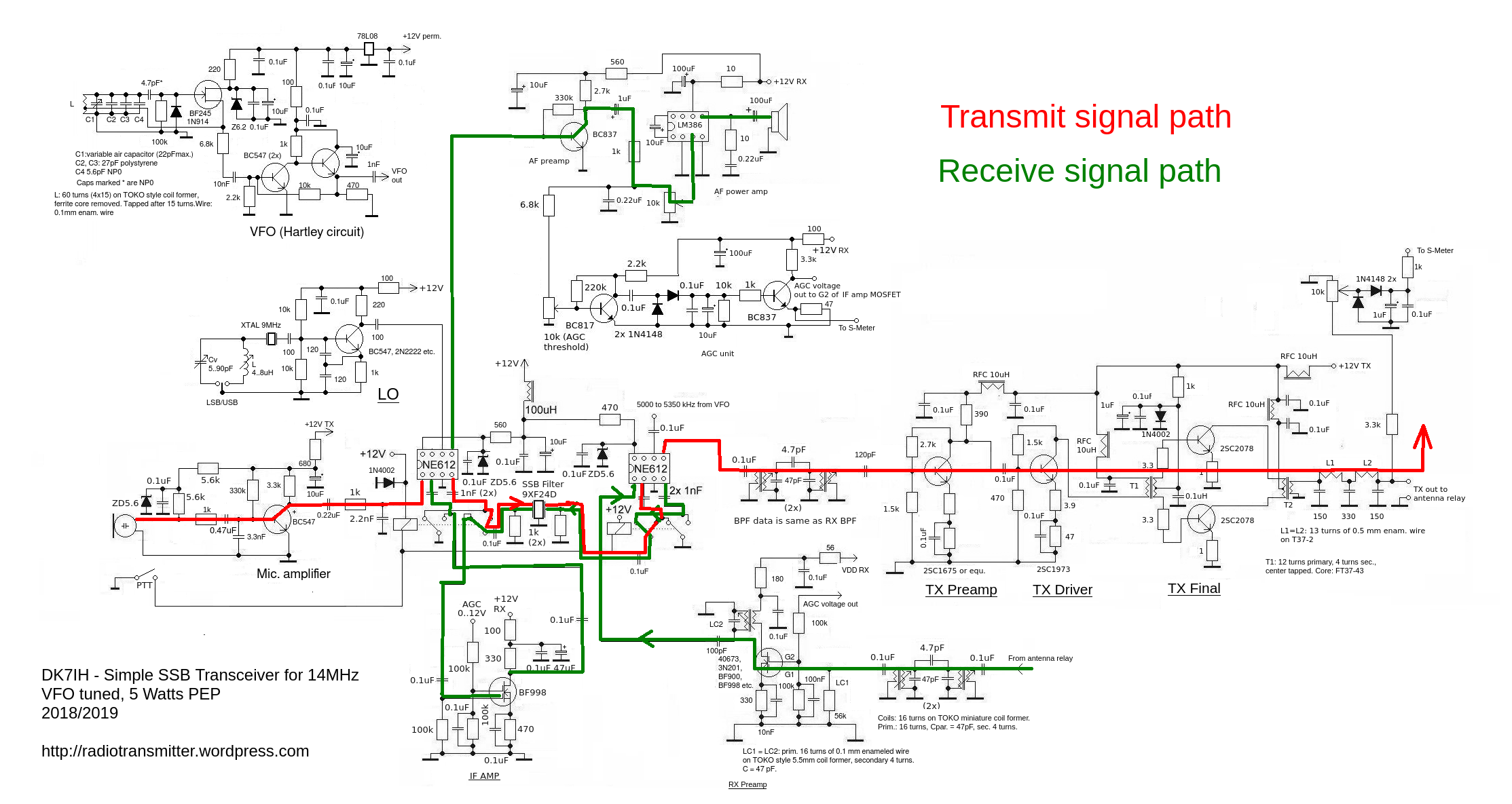
The mixer that is used together with the microphone to produce the DSB signal by mixing the audio signal with the local oscillator (LO) also serves as the product detector on receive by mixing the interfrequency with the LO. Correct signal path is set with the two relays depending on the fact you are either on transmit or receive mode.
The same principle is for the other mixer. It is transmit mixer or receive mixer, depending on the position of the relays.
The relays connect the SSB filter either to the input or the output of a distinct mixer. A graphical presentation should make it clear:
RX amp and interfrequency amplifier
These 2 stages are more or less the same. They provide 2 to 12 dB of gain depending on the AGC voltage applied to gate 2 of the dual gate MOSFET. In this version of the radio a potentiometer of 20kΩ is used to have the possibility to lower the DC voltage manually, by doing this an MGC (manual gain control) is achieved in a simple way.
Audio amplifier
A bipolar transistor and the inevitable LM386 amplify the filtered audio signal from the product detector to a volume that can be discerned even in a louder environment. The audio low pass filter prior to the AF preamp should be selected due to the users individual preferences concerning tone pitch of the audio signal.
RF power amplifier
This is more or less my standard power amplifier for small QRP rigs. I put stress on linear amplification, so I use emitter degeneration and negative feedback in collector circuit to get best IMD3 results. Even if the circuit could deliver one or two more watts I let the output power level at about 5 watts pep.
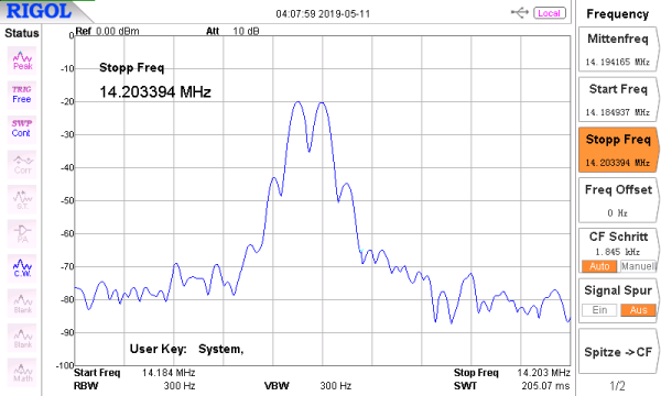
Here ist the result of a dual tone modulation:
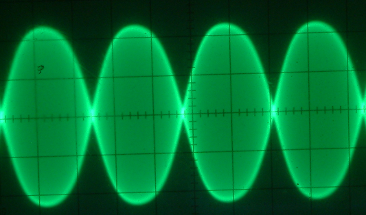
Voltage division is 10 volts per cm, so this is 45Vpp which equals to about 5 watts max. peak output. Quite OK for QRP. And here is the spectrum of a 2-tone-modulated signal:
Practical setup
The whole transceiver is built on a 12×8 cm Veroboard (4.7″ x 3.1″). There is only one layer. The cabinet is 4 cm high (1.55″), 14 cm long (5.5″) and 9 cm wide (3.5″).
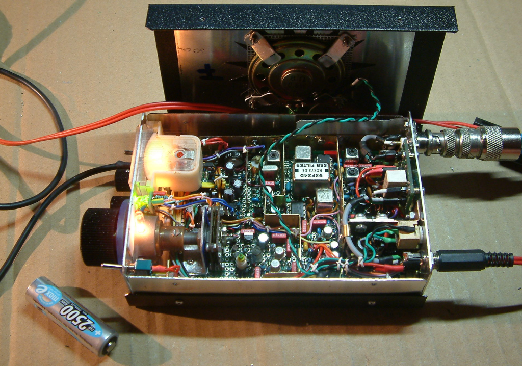
Left the vernier drive with the homemade capacitor attached. Left of the 9MHz filter you can see the LO, more far left the S-meter (from an old CB radio) hiding the audio amps. The 2 mixer ICs and the relays are sited around the SSB-filter. On the right side the power amp partly hidden by the DC switching board.
Well, that’s the story how a nearly failed project was saved from the scrapyard and came to life by carefully searching the faulty element in the circuit.
Vy 73 de Peter (DK7IH)
As you know Peter I used the same dual SA612 circuit in a 4-band transceiver, for SOTA and portable use, I call it Summit Prowler 6. I’m impressed by the performance of this simple design. With the AGC I can leave it running on the bench all day and it copes wirh signals weak and strong. It’s a lot of QRP radio for a small amount of parts and hassle. I relay-switched the BPFs between receiver and transmitter, but I wouldn’t bother in a monobander.
Oh yes, I used a Nano/si5351 combination, I have not tried my hand at an analogue VFO. Maybe sometime. I like the idea of running the VFO 24×7, so that it never has to cool down, the rest of the rig can be turned on and off as needed.
On another note, it looks like the original designer used the MC3362 as a VFO. I am making up a little Rx wirh tjis IC, have you tried it?
Thanks again for your inspiration! 73 Paul VK3HN.
Hello Paul,
I have once also thought about letting the VFO run full time when the trx is connected to a DC power source. But I went back from that because I the realized that the time to stabilize is quite acceptable (about 5 to 10 minutes). And even when the VFO draws only very low current from the battery, it will significantly discharge compared to only self-discharging the accumulator by the interior process of migration of ions inside.
The MC3362 I have seen but have not used one yet. Maybe for a future project. 😉
73 de Peter
True, 5 to 10 minutes for warm up is no penalty. I’m playing with a MC3362 on a little board so will report back! 73, keep up your great work! Paul VK3HN.
Hi Peter
Another great QRP project.
As a matter of interest where do you get your 5mm toko formers from
73 John ZL2TCA
Hi John, thanks for the positive annotations! 🙂 The coils are from German vendor pollin.de:
https://www.pollin.de/p/einstellbare-induktivitaet-3l-fe-349-250512
Edit: Formerly I bought them from AliExpress but the link is not more available. Maybe you can find them by using the search function.
vy 73 de Peter
Hello Peter,
I have browsed all you posted projects and I’m impressed with them all. Of particular interest is this one. With your modifications, how high would this design go? I have several Toko and other coil formers but I would like to know the final inductive values you use when you wind your coils, I don’t see that listed in your projects.
I have purchased several Dual-Gate MOSFETs over the years and now I’ve found a use for them. Thanks for all the posted designs and work you have done to optimize them.
Thanks,
Jim
Hi Jim,
thanks a lot for your mail and the compliments on my work. I try to answer to your question on coil data. I have developed a standard scheme of coils for the amateur hf bands except from WARC bands using the small TOKO coil formers shown in my projects. This scheme can be found in this picture:
https://radiotransmitter.files.wordpress.com/2019/06/coil_set_toko.jpeg
It states the complete data for a 2 LC band pass filter. Hope this is helpful for you.
Hint: “Code” is my internal coding putting dots with a marker pen on the bottom of the coil to make later identification easier. 😉
Wire diameter usually is 0.1 mm for the coils for 160 to 40m and 0.2 mm for the rest.
vy 73 de Peter
Peter, in circuit diagram, base of AF Preamp transistor could be missing a 0.1u coupling capacitor 🤔👍 regards Paul VK3HN.
Thanks Paul, you are absolutely right. I revised the schematic and reposted it. TNX again es 73 de Peter!
👍
Hello!
Perfect project!!!
I saw schematic and don’t find number of turns for T2 and what kind of core you used for it? Please write this parameters.
Regards Dima UT3UHR.
Hi Dima, thanks a lot for the comment. T2 is a BN43-202 pig nose core. Ratio is primary 2 turns center tapped, secondary 4 turns of 0.6mm enameled copper wire. Vy 73 de Peter (DK7IH)