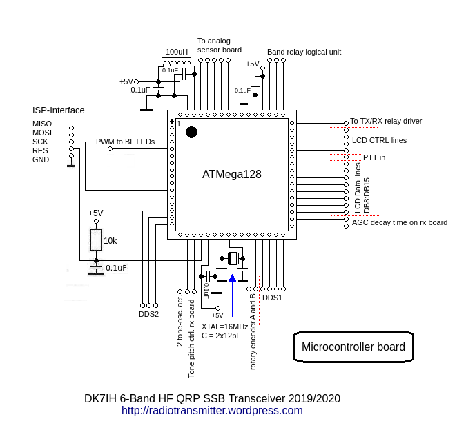
The heart of this transceiver is an ATmega128 microcontroller (MCU). It controls the vast majority of functions within the radio. E. g.: Frequency generation of the 2 DDS systems, audio tone and AGC decay time, T/R-switching, the presets for transmitter gain on the 6 bands independently, display and panel lights etc. etc.
And, due to usage of a parallel interface for the LCD (8 data lines and 4 control lines) an MCU with sufficient ports had to be used.
First I started with the SPI version of the LCD (ILI9341). This LCD has a high resolution of 240×320 dots. Driven by a relatively slow 8-bit controller like an AVR and the LCD driven in serial mode the performance was inferior.
Next I found that the same LCD is also available with a parallel interface. Then called CP11003. This one uses 12 lines (8 data and 4 control lines minimum), which made it mandatory to use an ATMega128 controller. To enhance speed and performance this one is clocked by a 16 MHz crystal. A touchpad is also integrated, but not used in my application.
Source code in C programming language can be downloaded from Github.
Vy 73 de Peter (DK7IH)
Hi Peter , Your design looks great. I have just wriiten all the software to the at128a. I imagine the tuning is the by the rotary encoder ,but canot get my head round how band change is made ,probly due to old age Hi ?ny thanks
Many thanks Paul G4AIB
Hi Paul,
things are a little bit tricky. Band change is done by accessing the in-built menu. You have to adapt some values before you get access to this menu. Provided the LCD does work and you got a screen display:
If so, you have to adjust the function get_keys() for your specific microcontroller. Uncomment the two lines following “//TEST display of ADC value” in this function, reload the software to the uC and start it. You will see the ADC values delivered by the get_keys() function on the LCD. Press all the 3 buttons subsequently and note the respective values.
Now put these values into the definition line of the value_array:
int key_value[] = {39, 143, 280}; in ascending order.
Re-comment the 2 “//TEST lines” and reload the software to the controller.
Now you can access the menu funtions by pressing the key with the lowest of the 3 ADC-values (in my terminology this is “button #1). The menu item highlighted is altered by tuning the main tuning wheel and selected by pressing button #2. If you press button #1 you will get to the next menu item, #3 quits the menu.
If anything should go wrong, just mail me! (dk7ih@yahoo.de)
vy 73 de Peter 🙂