Abstract
This article will describe some design ideas that might be helpful in case the objective is building a medium power (i. e. 10 to 20 watts pep) radio frequency amplifier using a very compact design
The whole final amplifier for the broadband linear transmitter had to be packed into an area whose size is 5 by 11 centimeters.with approximately 2.5 centimeters in depth.
Because of limited space the power amplifier module had to be stacked using pin headers and connecting them with appropriate means. This effort resulted in two layers of circuitry:
- The transformers for in- and output, the bias circuit and the radio frequency choke for the DC power line
- The two power transistors (2SC1969)
Also a heat sink had to be planned.
Practical design of a compact medium power QRP RF linear amplifier
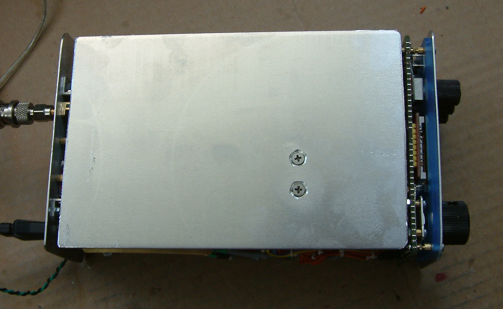
A large heat sink of aluminum covers the area of the underside of the transceiver:
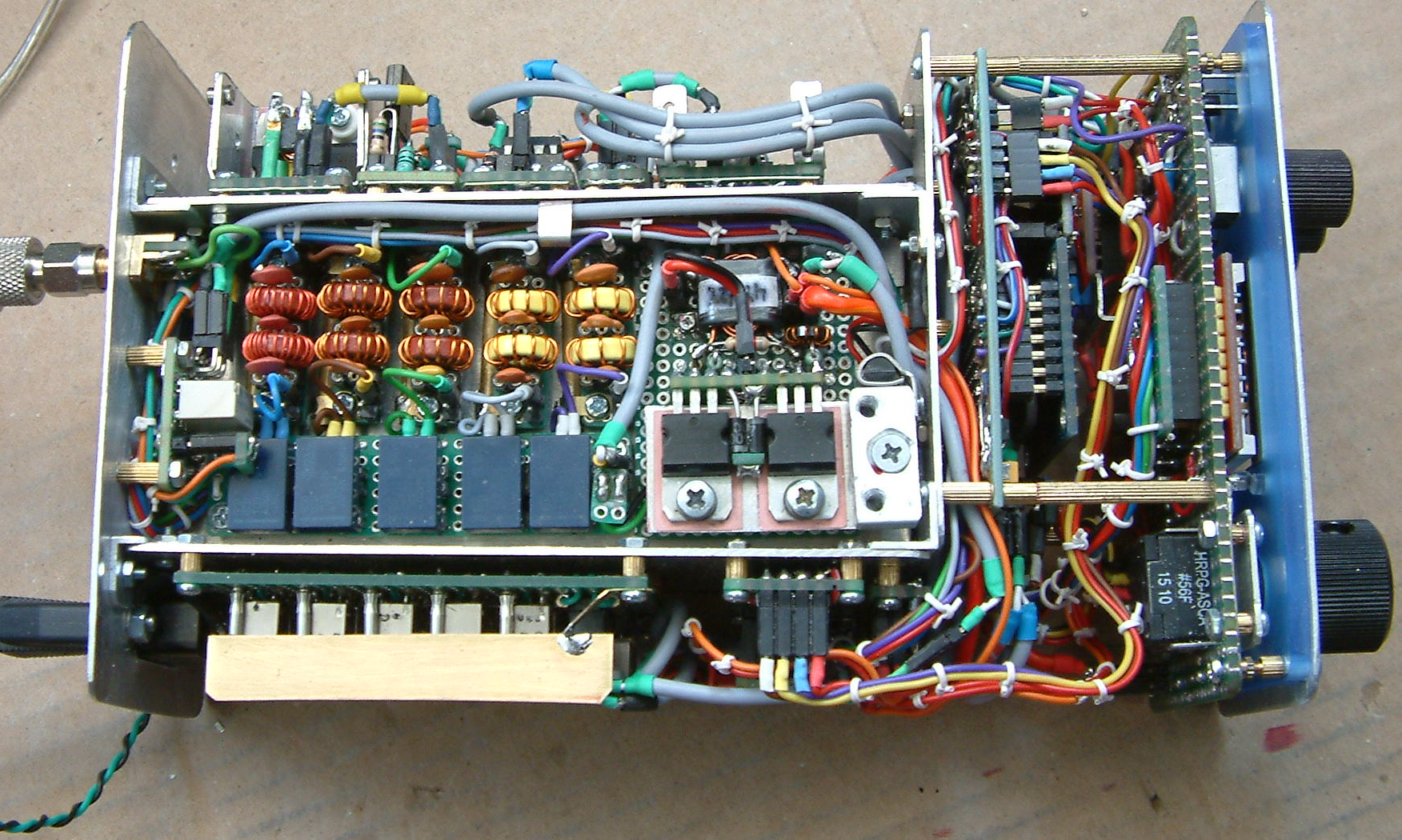
When removed, access to the power amplifier section is possible:
When removing the thick aluminum block containing the screw’s holes we see a support construction that holds the connecting block and the final transistors in place. Here also the temperature sensor (KTY81-110) can be spotted, attached and the rear side. This aluminum structure is the only thermal connection between the small sheet metal holding the transistors and the heat sink. But it turned out that temperature of the pa transistors rarely rises above 50°C even when long test periods are performed for adjusting the amplifier. So, this idea has proved to be a mechanical, thermal and electronically good arrangement.
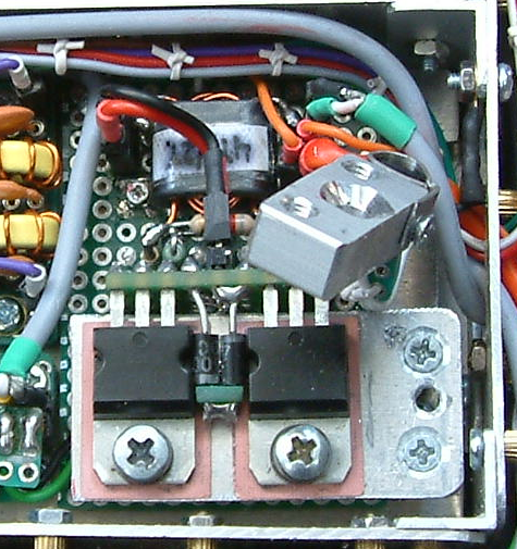
Between the pair of 2SC1969s the biassing diodes are visible which control the current for the current regulating transistor sited under the input transformer. Thermal contact is ensured by positioning the transistors extremely close to the diodes.
When removed, we can see the transistors mounted to a very small part of veroboard and connected to the “main board” with a row of socket strips.
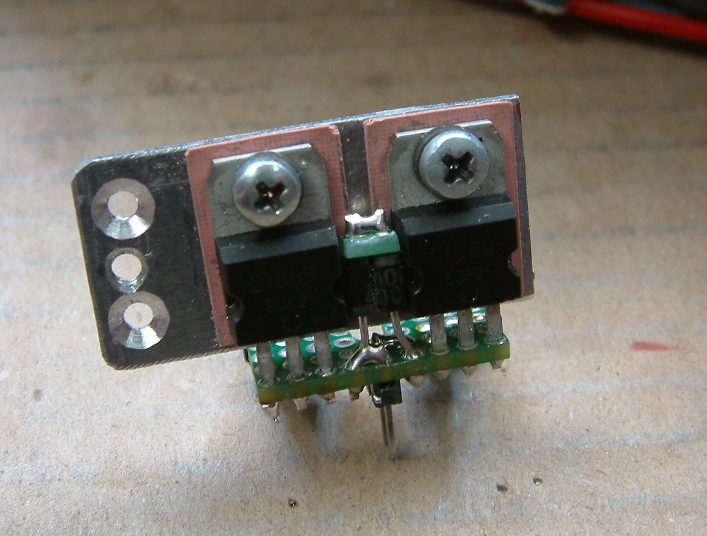
Underneath we see the output transformer made up of 2 stacks having 3 toroids FT37-43 glued together with 2 component glue.:
Because of limited space the connection to the low pass filter board is done with hookup wire. With just a length of 2.5 centimeters this is not a real problem.
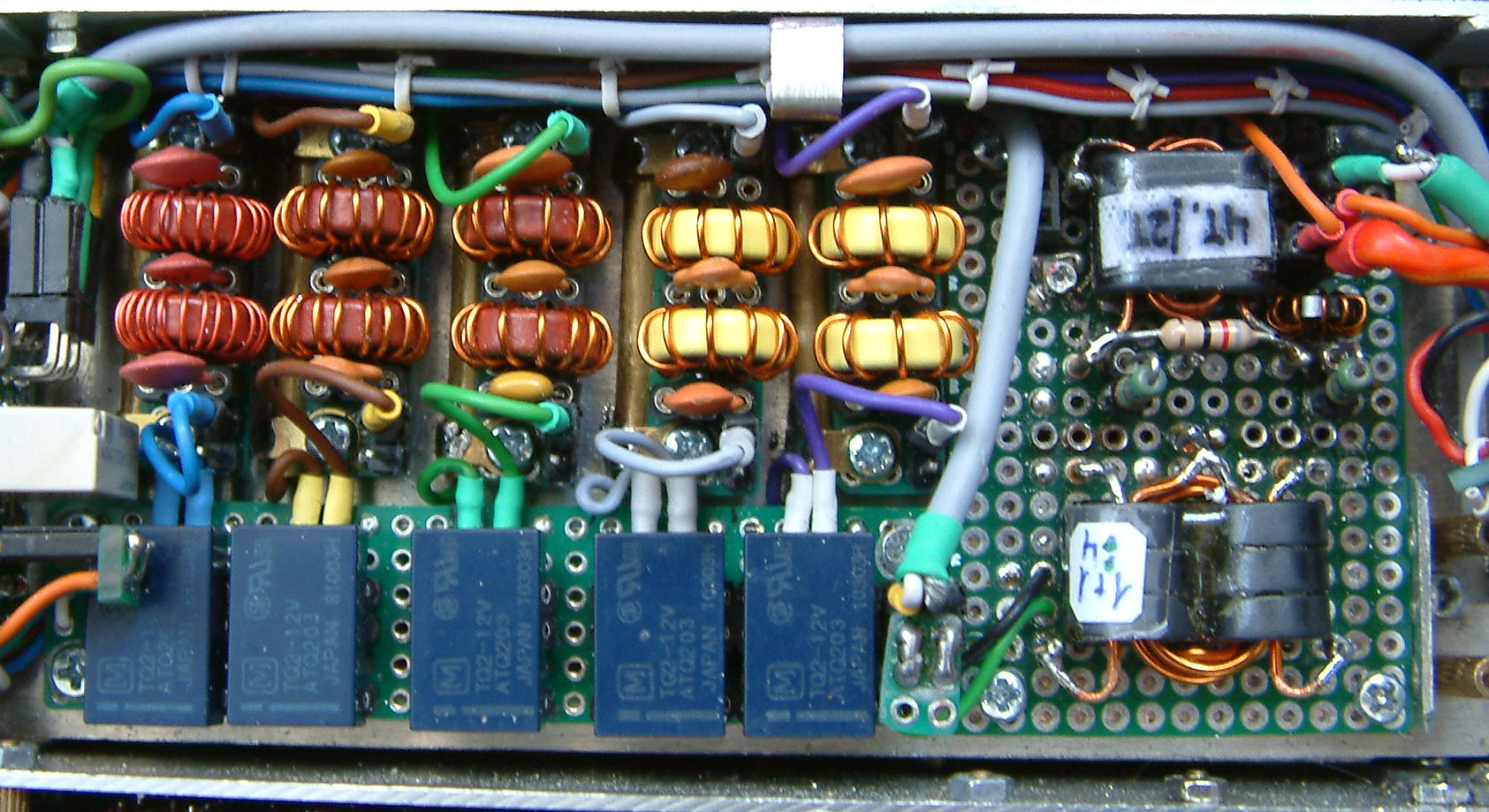
The five band switch relays are connected to 5 separate veroboards (which makes changes of e filter very fast) containing each one filter for one band. Every veroboard is held in place by 2 small bolts with M2 specification. Between the veroboards small brass tubing pieces can be observed which serve as “shielded” lines for the longer leads going to the end of a respective filter. Inside the tube there is another piece of 1.1 mm diameter PVC insulated hookup wire.
Color coding of the various bands is unique over the whole transceiver.
Very far on the left side the transmit-receive relay has been positioned. This one only is for switching the antenna socket between transmitter and receiver. DC switching is done with small p-channel MOSFETs sited behind the LCD display and will be discussed later.
So, that’s all for today, thanks for watching! 😉
73 de Peter (DK7IH)