Introductory article of this project
This is some sort like “Copy & Paste”, a useful mean if you want to create a doctorate, like the former German Minister of Defense Mr Guttenberg once did. 😉 I don’t want to achieve a doctorate but the receiver of this radio is more or less the same I have constructed for the Midi6-transcevier. So I just copied the schematics and put down the changes in this paper.
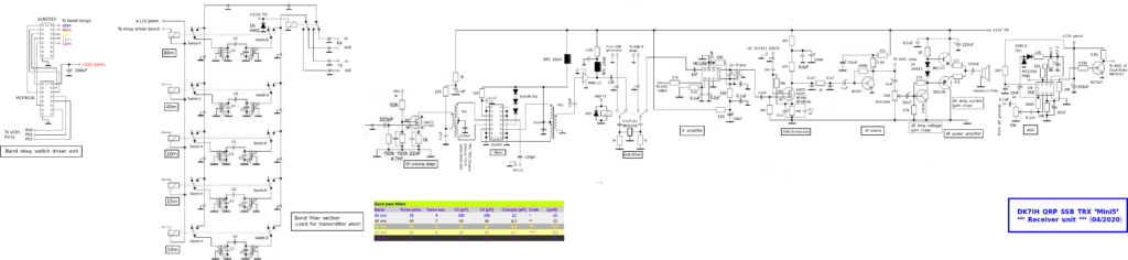
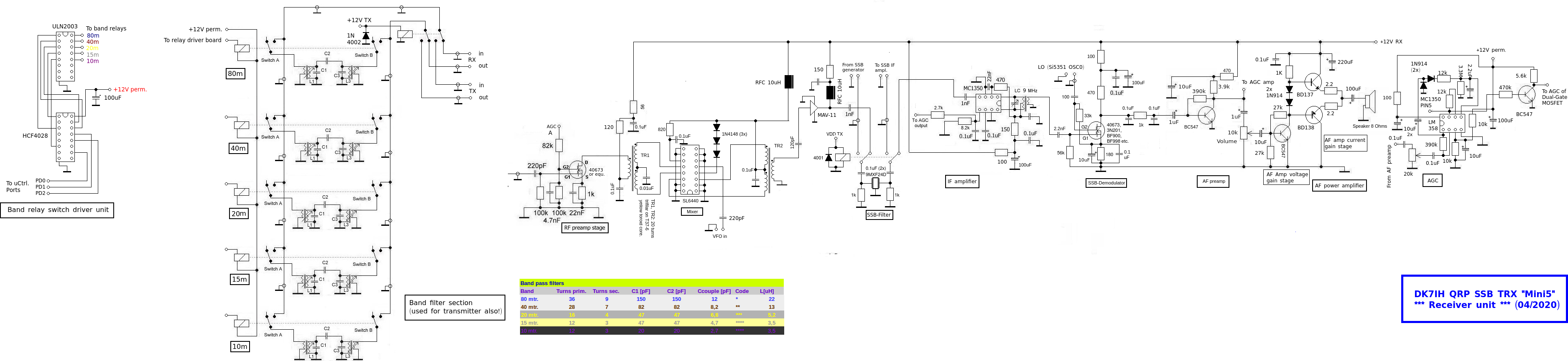
To see a full sized picture of the RECEIVER, please click here!
Starting the tour on the left you can see the band switch unit, beginning with a BCD decoder that converts a 3-bit pattern created by the MCU into a 5 line decimal output. The ULN2003 then is a driver designed for motor controls but it is very useful as a relay driver as well. Integrated clamp diodes and open collector circuit make it practical as a driver circuit for this unit.
Next is the band pass filter section. I still use relays for switching the respective filter because I found that it is the best way to keep unwanted signals low from passing the filter, provided you use relays that can serve this purpose., Here signal relays TQ2-12V by Panasonic have been applied. Coils are small TOKO style coil formers with 5.1 mm (2×2.54mm i. e. 2×0.1″) pin spacing.
RF preamp is equipped with a dual gate MOSFET like the BF900 or so. The “AGC” this time is to be manually, just connect the AGC input (which now is an “MGC” to say it correctly!) of the stage to a 10kOhm variable resistor allowing a voltage swing between 0 and 12 V and this will lead to a preamp stage with gain control in the range of 25dB. This variable resistor is to mounted into the front panel, just to be concise.
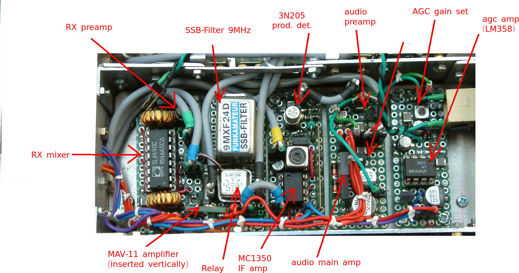
The receiver’s mixer is an SL6440 which has great IMD3 performance (about 30dB) and has been used instead of diode ring mixer. Some dBs of gain are achieved as well but not the amount you can expect from an SA602.
In practical terms the ic really proves what the manufacturer promises. On 40m e. g. with a large doublet antenna no IMD products are audible even when strong broadcast station are next to the amateur radio band. A really worthy trial with this receiver!
Due to the fact that the following SSB filter is used for the transmitter also, another signal relay switches the filter between the receiver and the transmitter branch.
An MAV-11 monolithic amplifier follows the filter to lift the signal a little bit.
Next the MC1350 video amp is installed to do the major amplification with the interfrequency signal. It is gain controlled by the AGC circuit on the right side of the schematic. Gain is minimum if AGC input is around 7V or higher.
The product detector is a dual gate MOSFET which is only there because this one has a slight amount of gain and does not consume much space on the tiny boards.
The audio preamp stage is also very simple, just a bipolar transistor with negative feedback applied via a large resistor (390k) also biassing the unit to an appropriate value.
The audio main amp here is not an ic (like the inevitable LM386 e. g.) but it is a push-pull arrangement using 3 bipolar transistors. The stage that enhances the voltage is designed with a BC547, the stage that is bound for current amplification uses a pair of complementary transistors (BD137 -NPN- and BD 138 -PNP-). Audio power is about 1 Watt which is suffice for a small radio.
AGC uses an operational amplifier, any type like the LM358 will work great. The LM358 contains two identical amplifier stages. The first is used to bring the audio signal to a certain level, then rectifying this voltage and subsequently bringing it into a time constant consisting of a charged capacity (2.2uF) and a discharging resistor (3.3M), The circuit has very fast response, so there is no annoying “plopp” when a strong signal breaks in) and the decay is very soft.
The second stage just works as an instrumentation amplifier putting out up to 12V to control the input of the MC1350 at PIN5.
To end this article let’s have a look at the practical setup of the receiver:
Vy 73 de Peter (DK7IH)
Hello Peter
What are the specs of the transfo at the output of the MC1350?
Hi Alain, sorry for answering so late, I don’t watch the blog regualarly and sometimes miss info that some has posted.
So, here is the answer: The transformer is wound on a small TOKO style coil former, primary are 16 turns, secondary are 4 turns.
Vy 73 de Peter (DK7IH)
Hello Peter
What are the specs of the transfo at the output of the MC1350
Hi Peter
What are the specs. of the transfo 9MHz after the MC1350 ?
Hello Peter
Thank you and another question. There is a mismatch that I don’t understand. The output impedance of MAV11 is 50 ohms and the input of the ceramic filter is 1k. The resistance of 1k at the input of the filter resistance should not be in serie ? or better use a transformer 50/1000 ohms
A French SWL beginner ;o)
Hi Alain,
thanks for your question. I allow mismatches to a certain degree if there is plenty of gain in the circuit. This is the case with most of my receivers and helps to reduce tendency to self-oscillation and avoids exceeding the gain swing of my AGC circuits. Mismatch reduces the gain and does not push the AGC to its limits. Mismatch might lead to lower IMD3-performance when it occurs near mixers so I try to avoid that.
With transmitters I am more keeping an eye on well matching the stages because I use 3 stage transmitters mostly that are designed to produce 5 watts pep. There every dB counts. 😉
Vy 73 de Peter (DK7IH)
Hello peter, I am following your assemblies with great interest and mainly the MINI5 receiver unit.
On the AGC the lm358 does not seem to be powered, I think of an oversight.
73 F5ETM
Hello Jean-Pierre, yes, you are absolutely right! A momentary laps of reason, like always. 😉 Thank you and the file has been corrected! Merci beaucoup! 73 de Peter
Hello peter, good morning, just a question: can we connect the s-meter in parallel to the output via MC1350 of the AGC. thank you so much.
73’s
Jean-Pierre F5ETM