As mentioned in the introductory article to this radio the digital components in this transceiver are pre-manufactured modules that have only been put together in a more or less sensible way. ;-). These modules are:
- AD9850 as variable frequency oscillator (VFO), China made no-name board,
- Si5351 as local oscillator (LO) produced by “Adafruit”,
- Arduino Pro Mini w. ATMgea328p as Microcontroller Unit (uC, MCU), no-name
- ST7735 colored LCD, no-name,
- MCP4725 as digital-analog-converter to preset transmitter gain via MCU, “Sparkfun” clone from China, no-name
All units are able to run on 5V which made it easy to layout the schematic because only one 5V/1A voltage regulator had to bu used.
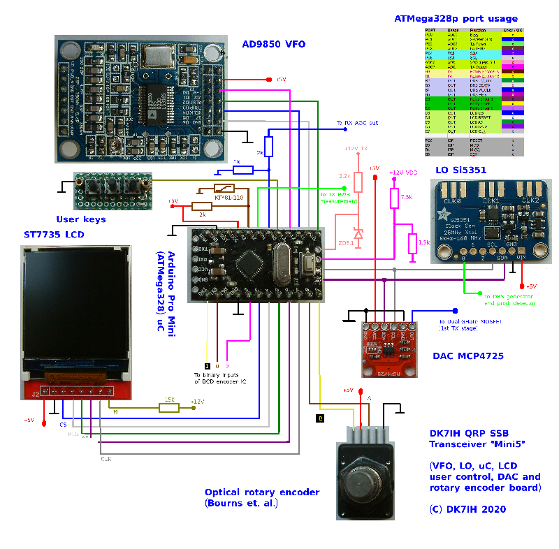
To watch a high resolution version (4.2MB!) of the wiring scheme, please click here!
Hints:
a) The lines for ISP (MOSI, MISO, SCK, RESET and GND) have not been drawn but the location to the respective ports is mentioned in the table sited in the right top corner. Reset rquires 10kOhms to +5V and a 0.1uF cap to GND.
b) Certain clones of the MCP4725 DAC module will produce conflicts with the I²C/TWI-address of the Si5351 LO module. Original “Sparkfun” boards come with I²C/TWI-address 0x60, 0x61 or 0x62 (depending on literature/web resource you get this information from).
This address is set by the manufacturer AD inside the hardware on customer’s demand. On the other hand the Chinese made modules I am using have basic address 0xC0 which is the address of the Si5351 also. Thus this leads to conflicts on the I2C/TWI-Bus. One solution is to close a solder bridge to +VDD on the very tiny DAC-board which will set address to 0xC2.
c) For the 4(!) user switches (not 3 like in the photo above!) the pull-up resistor on PORT PC0 is set on. There are is a resistor (in the range between 560 Ohms and 2.2 kOhms) with each switch, that pulls voltage to GND when the respective key is pressed. This leads to a voltage drop at the analog input that will be detected by the ADC channel.
This voltage drop depends on the pull-up resistor and on some other factors so it must be determined for every controller setup individually. To solve this, in the respective functionthat returns the numeric value for the key pressed there is a small commented code that you have to de-comment temporarily:
//Read keys via ADC0
int get_keys(void)
{
    int key_value[] = {39, 76, 103, 135};
    int t1;
 int adcval = get_adc(0);

    //TEST display of ADC value
    /*
        lcd_putstring(0, 5, " ", 0, 0);
        oled_putnumber(0, 5, adcval, -1, 0, 0);
    */
    for(t1 = 0; t1 < 4; t1++)
    {
        if(adcval > key_value[t1] - 10 && adcval < key_value[t1] + 10)
        {
            return t1 + 1;
        }
    }
    return 0;
}
Restart the software, press every key, put the indicated key value into the code (line 4) and re-comment the orange lines when fnished. Next re-upload the software to the controller.
d) Source code in C is available on my Github repository. Please note that even if an Arduino Pro Mini MCU board is used, the code is not designed for the Arduino “world”. It does not use functions of the Arduino environment and may not function with the Arduino bootloader.
To compile the C source and generate the HEX-File you need the GNU C Compiler either for Windows or Linux.
73 de Peter (DK7IH) and thanks for watching!
I see you’ve written your own handlers for the Si5351 (including the atmega TWI interface), and the st7735 LCD. I wish you’d have separated these out into their own library files, and used header files to define all the function accesses, it would make it easier to re-use your code.
I’ve been mostly using the Arduino libraries for this kind of stuff, though I have also written my own AVR code using make, and avr-gcc. Arduino libraries tend to be C++ class wrappers around the handler code, I think that the class based libraries have their good points, but there is nothing wrong with function based libraries.
I suggest the following mods to your TWI code to add error status to writes, and read functions.
/*************************************************************************
* Send one byte to I2C device
*
* Input: byte to be transfered
* Return: 0 write successful
* 1 write failed
*************************************************************************/
unsigned char( twi_write(uint8_t u8data)
{
TWDR = u8data;
TWCR = (1<<TWINT)|(1<<TWEN);
while ((TWCR & (1<<TWINT)) == 0);
// check value of TWI Status Register. Mask prescaler bits
twst = TW_STATUS & 0xF8;
if( twst != TW_MT_DATA_ACK) return 1;
return 0;
}
//read a single char
char twi_read()
{
TWCR = (1<<TWINT) | (1<<TWEN);
while(!(TWCR & (1<<TWINT)));
return TWDR;
}
//read multiple characters. Call this function until the next to last character is read,
// then call twi_read() for the last character desired.
char twi_readm()
{
TWCR = (1<<TWINT) | (1<<TWEN) | (1<<TWEA);
while(!(TWCR & (1<<TWINT)));
return TWDR;
}
Hi there, just an update: I found that the AD9850 draws about 100mA current what I consider too much for a portable QRP transceiver on receive. Thus I tested the Si5351 again as the VFO and I made the signal level adjustable by installing a trimpot and got an interesting result. When not exceeding the appropriate drive level for the RX mixer the spurs completely disappear. 3Vpp were too much for the SL6440 mixer. This result is great because I save battery energy and the rig got smaller because I save the respective space for the AD9850 board.
vy 73 de Peter
You can also reduce the output current from the Si5351 in software. IIRC, you set all the outputs to the max current of 8ma, but it can be set to about 1/3 the output. Also, some mixers may not like the square waves, a simple low pass filter between the Si5351 and the mixer might reduce spurs too.
the excess current of the AD9850 module can be due tot the fact that the 125 MHz crystal oscillator on board is a 3.3 V type. So either redruce the supply voltage of tthe vomplete module to 3.3 V but then risk that the DDS itself is operation below its specified operation range or desolder the xtal osc and use a rarly avaliable 6 V osc instead or do some voltage dropping circuitry to Vcc.
Running a 3.3 V Osc at 5 V will not only caus large frequeny drifts but also destroy the osc. Please have a research in the internet!
Thanks a lot, will try that soon! 😉
Hi peter
A little bit of trouble when I compile to see the value of adc0
“oled_putnumber” does not exist so I think it is “lcd_putnumber”
And the compiler said there were too few arguments for “lcd_putstring” and “lcd_putnumber”
Sorry, I have absolutely no knowledge of C language
Hi Alain, no problem, if you just tell me if would like the parallel or SPI version of the code I can mail a working version to you 73 de Peter
Hi Peter
The SPI version
Thank you
Hi Alain, I have put the code to github.com:
https://github.com/DK7IH/ILI9341_LCD_SPI_Version
If you have any question, just ask! 73 de Peter
Hi Peter
I think i’m not clear
I would like the correct value for the “lcd_putstring” and “lcd_putnumber” for the test display of the ADC value in the code “Mini5.c” to eliminate compilation errors
Hello Peter
Found the solution.Replace “oled_putnumber” with “lcd_putnumber”, and added “WHITE” and “backcolor” to the two lines and now the compilation is Ok
Hi Alain, think so. I always use “lcd_” for standard lcds and “oled_” for OLEDs like 1306. But I always have different parameters to hand over depending on the respective device. Hope you get along with my code. 73 de Peter (DK7IH)
Peter
I’m thinking of adopting your transmitter gain control mechanism in a 5-band transceiver under development. I am thinking of including a dual gate MOSFET pre-driver, and control its gain at gate 2 from the DAC, just as you have done. My question is, did you consider trying one of the ATMel MCU ADC PWM outputs and a resistive network to realise a variable voltage in the range of near zero to near 5V? Or is the use of an explicit DAC such as the MCP4725 needed? Your thoughts appreciated.
Paul VK3HN.
Hi Paul,
yes I have thought of this idea. Integration circuits are possibly a diode, a capacitor and a discharging resistor (if necessary). That would be a simple solution but I haven’t used it because I wanted to try the I²C DAC. But I think theoretically it should work.
Another idea I had was to switch 5 (or so depending on the number of bands you have) voltage trimpots (separated from the other ones by using diodes) and one these always switched for the respective band by a switching transistor. But I have found the MCP4725 more interesting.
Vy 73 de Peter
Thanks for sharing your ideas, all are good and would work. In fact the 12 bit DAC is overkill, but an interesting module to try out. Have you thought about implementing a digital AGC? One of the MCU’s ADC would do sampling, then use the DAC to control an AGC line. AGC characteristics set in software.
Getting sufficiently fast attack may be the challenge while the main MCU loop handles all the other tasks. But even a little bit of AGC attack softness could be tolerated while tuning. I wonder how ‘fast’ a microcontroller and/or ADC would be needed to make this work. Another possibility in this amazing world of homebrew receivers and transmitters designed from available parts.
Paul VK3HN.
How about using the ADC to same the microphone input to implement VOX?
Or use ADC on a line off the mic amp to implement an ALC to smooth out voice peaks. Not particularly important on QRP transmitters but Peter has built several 50 watt rigs, at this power level we are starting to get to the point where ALC may be needed to preserve linearity and signal quality. The other scenario that may drive the need for ALC is if these exciters were paired with a higher power external linear amplifier.
These ideas are possible, but they do contribute to complexity, drive changes in the choice of MCU and other hardware. At a certain point, the resulting transceivers are no longer ‘simple’.
Peter and Paul,
Are you aware of the new MicroChip AVR parts (AVR128dx series, and atmega480x series? The ‘128dx is available in a 28 pin dip, and has a 10 bit D/A built in. (128kb flash in a 28 pin package! The 48 pin device has the same pinout as the ‘4809 on the Arduino Nano Every, it you feel up to desoldering it and doing the upgrade!)
The ‘4809 is available in a 40 pin dip package. Breadboard friendly!!! I’m playing around with the AVR128dx48 curiosity nano dev board right now. It’s not yet supported by any Arduino cores, but I’m using MPLAB-x IDE which works under Linux (unlike AVRstudio). The MC Nano dev board has a built in programmer, but their SNAP and PicKit4 work too, along with the Atmel ICE. I have the latter two.
Hi WA2MZE, just had a look at the 4809 device. Looks interesting on the first glance. The dive seems to be slightly faster than the ATMega168, …328 etc. Have downloaded the data sheet and have the device in mind for new developments.
vy 73 de Peter
Hi WA2MZE, thanks for alerting me to the 4809. I haven’t studied or played with MCUs to the same level as has Peter, but I’ll watch with with some interest. The number of Nano alternatives is overwhelming now.
Hi Peter
I’m not familiar with the digital world and C code. So I used the hex file you provide and loaded it into an Arduino pro mini but it doesn’t work
Blank screen and no I/O activity?
I did a test by just wiring the promini to the LCD display (ST7735) to avoid any further problems but nothing?
But in this case, can the program run without any LO VFO attached and no informations to the AIN inputs?
If so, then there is a problem with the hex file
Best regards
Hi Alain, the problem can occur because the original bootloader in the Arduino might still be present. I used an Arduino Pro Mini but eliminated the Arduino bootloader and use in the “native mode” as a basic ATMega328. Programming is done with AVRdude.
vy 73 de Peter
Hi Peter
What are the values of the fuses, because always no activity on the 328
Hi Peter
Did you use the hex file to flash your uC ? because I can’t made it working after several tries :o(
Hi Alain,
yes the procedure is always the same: Compile the C-Code to HEX and upload the HEX with AVRdude to the uC. vy 73 de Peter
Hi Peter
Sorry, but still unable to work. Now no bootloader, trying several config of fuses….. Can I use the same “avrdude instruction” finding in your “re-engineering 1st shirt pocket” code for the fuse settings?, because it is the same MCU.
Thank you
Hi Alain, from my point of view the settings posted there should work. vy 73 de Peter