by Peter Baier (DK7IH)
After years of indoor model-railroading I have started building a medium-sized garden railroad this spring after having completely redesigned our garden by removing trees and therefore getting space for the railroad layout. Normally model trains are track-powerd. For outdoor operation this is not the best idea because due to weathering tracks’ metal surface (usually made from brass) covers with oxide and needs regular cleaning before operation.
An alternative to avoid conductivity problems is for example using live steam locos. If you additionally want to run diesel model locos, electrical power is the best idea since there are no so small working diesel engines.
Abstract
The following article describes a radio control unit that can control an electrically powered large scale model loco. It uses ready made breakout board containing ISM rf modules with a lot of built in functions. One of them is the RFM12B made by HOPE RF electronics in this case operating on the 433MHz ISM radio frequency band. Other bands (395, 868, 915 MHz) are possible by choosing an appropriate version of the module. Also a fully working software in “embedded C” code is supplied, programmed particularly for AVR microcontrollers.
Multiple locos can be addressed by choosing a respective ID byte in transmitted string.
The RFM12B
RFM12B is a ready made break out module that carries an Si4421 chip by SiliconLabs. It is available either for 315, 433, 868 and 915 MHz operation. VDD is 3.6V max., 3V is recommended by the manufacturer. The unit can work either as a transmitter or a receiver. Configuration is done by software.
Hardware
The PC boards for the various radio frequency bands are the same, the only difference is found in the output filters. These are tuned for the respective band the module has been designed for. The RFM12B is about being sold out, the successor is called RFM69CW which is pin compatible but software has to be altered slightly.
There are (or have been) two versions available: An SMD type board (2mm pitch) and a DIP board (2.54mm/1″ pitch):
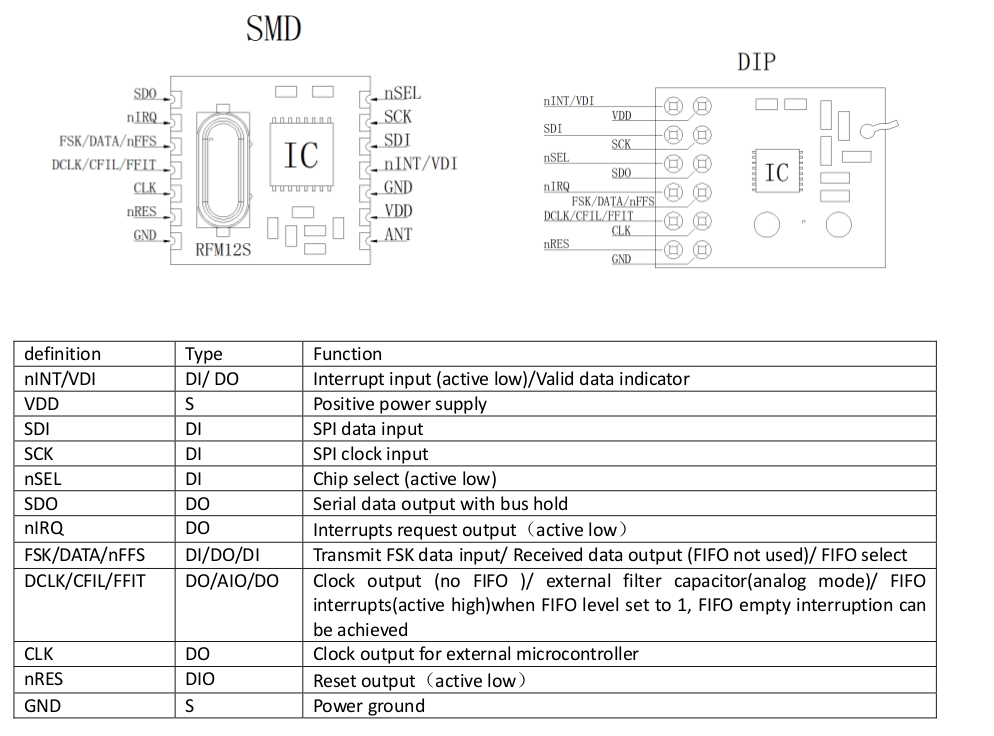
Source: HopeRF datasheet
The Basics
The RFM12B supports two major modes of operation:
- High level data communication using a FIFO (first in-first out) function block included in the chip’s MCU.
- An FSK mode that can be used to transfer digital “raw” data.
For this RC circuit I have used the FSK mode together with the UART series communication module integrated in the AVR controller.
Loco motor is driven by a pulse-width-modulation (PWM) circuit whose signal is derived from one of the ATmega’s PWM output (OCR1A). A 2-stage driver made from simple NPN-transistors powers the electrical engine. Power MOS-FETs are not an alternative here instead you use types that provide full power through Source-Drain even with lo Gate voltage (3.3V approx.).
How the RFM12B communicates with your micro (MCU)
The communication between internal Si4421 and external microcontroller is established via an SPI interface. You can either use the integrated functions from the MCU that you have at hand (I am using AVR controllers, here an ATmega328P is applied), or you can write your own code for a simple SPI interface. If you use internal SPI functions within the AVR controller, keep in mind that this mainly is an 8-bit communication structure wheres with the RFM12B you need 16-bit (or more) transfer. This my solution:
int spi_send_word(unsigned short txdata)
{
  int t1 = 0;
  int r = 0;

  PORTD &= ~(NSEL);
  _delay_us(TWAIT);

  //Send ID byte to define register
  for(t1 = 15; t1 >= 0; t1--)
  {
        PORTD &= ~(SCK);
        _delay_us(TWAIT);

        if((1 << t1) & txdata)
        {
            PORTD |= SDI;
        }
        else
        {
            PORTD &= ~(SDI);
        }
        _delay_us(TWAIT);

        PORTD |= SCK;
        _delay_us(TWAIT);

        if(PIND & SDO)
        {
            r += (1 << t1);
        }
        PORTD &= ~(SCK);
        _delay_us(TWAIT);
    }
    PORTD |= NSEL;
    return r;
}
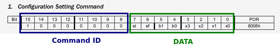
The data format used for exchanging data between the MCUs is not very complicated. In most cases 16 bits of data have to be transferred via the four SPI lines. The first bits (varying from command to command) are a CMD identification sequence, the remaining bits are intended for further specification of the respective command. See datasheet for details!
SPI uses 4 lines. These lines are:
- nSEL: Active low for marking ongoing SPI communication
- SCK: SPI clock signal, lo to hi when data is present
- SDI: Data from External MCU to RFM12B
- SDO: Data received from RFM12B
The remaining line applied is the FSK/DATA/nFFS line, that transfers “raw” data exchanged between the two boards.
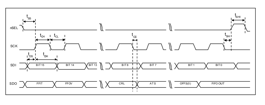
The timing diagram is SPI standard:
Software
For using the RFM12B ISM TRX module an initialization sequence is required. For the special purpose of this project this is:
 //Init Si4421
spi_send_word(0x8017); //NO FIFO => !EL,!EF,433band,12.0pF (1. Configuration Setting Command)
spi_send_word(0x8239); // !er,!ebb,ET,ES,EX,!eb,!ew,DC, FIFO (2. Power Management Command)
spi_send_word(0xA640); //434MHz freq. definition (n=1600) (3. Frequency Setting Command)
spi_send_word(0xC647); //4.8kbps (4. Data Rate Command)
spi_send_word(0x94A0); //VDI,FAST,134kHz,0dBm,-103dBm (5. Receiver Control Command)
spi_send_word(0xC2AC); //AL,!ml,DIG,DQD4 (6. Data Filter Command)
spi_send_word(0xC483); //@PWR,NO RSTRIC,!st,!fi,OE,EN (10. AFC Command)
spi_send_word(0x9820); // !mp,45kHz,MAX OUT*/ (11. TX Configuration Control Command)
spi_send_word(0xCC77); //OB1,OB0, LPX,!ddy,DDIT,BW0 (12. PLL Setting Command)
spi_send_word(0xE000); //NOT USED (14. Wake-Up Timer Command)
spi_send_word(0xC800); //NOT USED (15. Low Duty-Cycle Command)
spi_send_word(0xC040); //1.66MHz,2.2V (16. Low Battery Detector and Microcontroller Clock Divider Command)

_delay_ms(500);
spi_send_word(0x8208); // Turn on crystal
rfm12b_setfreq((433.92-430.0)/0.0025);
rfm12b_setbandwidth(4, 1, 4); // 200kHz band width, -6dB gain, DRSSI threshold: -79dBm
rfm12b_setbaud(19200); // 19200 baud
rfm12b_setpower(4, 6); // 1mW output power, 120kHz frequency shift
The full code can be loaded down from my Github repositry.
For defining transmitter or receiver in a specific application some lines more of code are required, you can find the in the code on my Github repo. (See “Software section” in this page later!)
Multiple receivers with one transmitter
This RC system allows up to 26 different receivers to be controlled with one transmitter. This is due to the data format used. Codes are transmitted as ASCII strings with binary data for start (Chr(2)), end (Chr(3)) and checksum of the transferred string.
Example: A string can look like this:
[2]A S=128[cs][3]
- [2] binary 2 marks the begin
- “A” determines the loco ID in the range A…Z
- “S=” sets the Speed
- “128” is the respective numeric value coded in ASCII (range 0..255)
- [cs] is a one byte value (binary) representing the checksum
- [3] binary 3 marks the end of the string
The Receiver
For both, transmitter and receiver, the schematic is nearly the same. We start with the receiver unit:
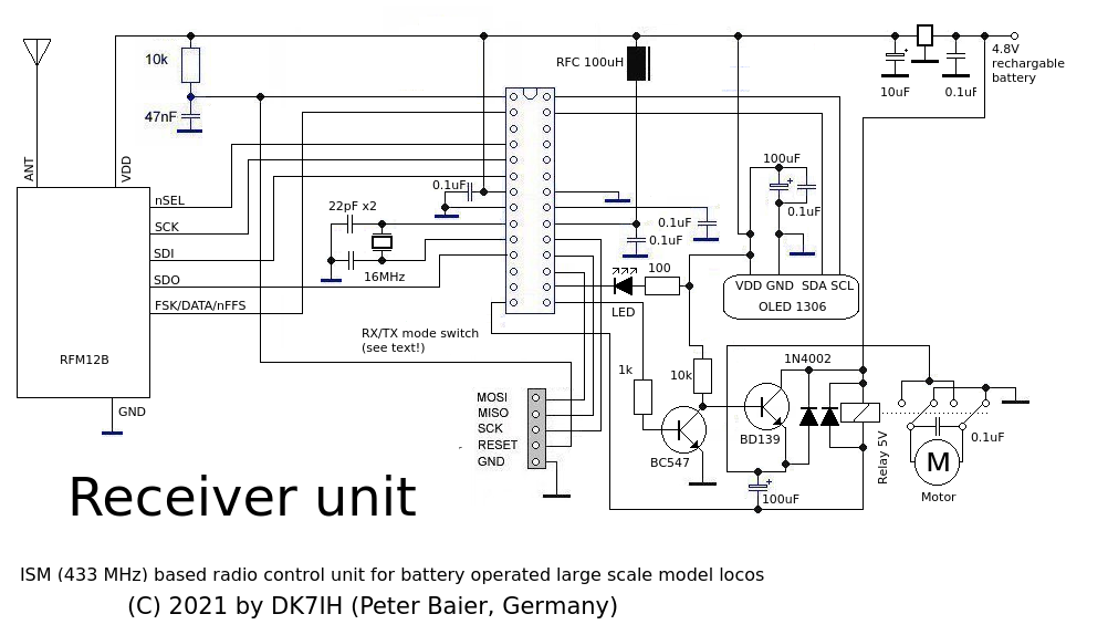
The RFM12B is connected via the 4 SPI lines to the MCU. The outputs are:
- The PWM out (OCR1A)
- A relay for forward/reverse operation of the loco
- A LED that indicates reception of a valid signal
There is an OLED display that can be ignored when the unit works fine. During development I have displayed data with that unit to check if all the functions are OK. You don’t need it for your loco instead you want the driver to watch TV when driving the machine. 😉
The circuit is equipped with a 4.8V battery pack that powers the loco’s motor and the circuit. Due to the fact that the digital equipment is restricted to 3.6 V max. voltage, this is decreased by a 3V or 3.3 V voltage regulator.
An antenna of appropriate length (about 17cm, 5 inches for 433MHZ ISM band usage) is required for maximum range.
The Transmitter
The circuit differs from the receiver’s slightly. No motor driver is installed, instead a linear variable resistor for speed control has been integrated:
![]()
The speed controller operates “center off”, the necessary calculations are done in the receiver when decoding the speed setting which is a numeric variable (n) between 0 and 255. If you have the controller in center position (n=128) the loco stops.
As you can see the UART lines RxD and TXD match to the FSK line of the RFM12B board respectively.
Software
The software is written in “embedded C” using the GNU CC for AVR microcontrollers. All necessary functions are included in one file. The code consists of two parts of C source, one for the transmitter and one for the receiver unit. You can access these on my Github repo:
https://github.com/DK7IH/433MHz_ISM_RC
The software also includes error checking and fail-safe routines. A checksum is built up from transferred data and in case of error (signal loss or heavy radio interference) the loco’s motor is stopped immediately.
Hints
The receiver is very sensitive to interference caused by the motor brushes. Thus a radio frequency blocking capacitor is mandatory very close to the motor. Even if there is error checking capability in the software, a severe amount of interfering noise can reduce range substantially. If problems persist it is also recommended to add two radio frequency chokes in series very close to the motor’s terminals which will eventually solve the problem. As I found out, the amount of noise is very much depending on the motor model you have in use. Thus, experimenting a little bit might be necessary if you have the possibility to do so which mainly should apply with scratch-built locos.
Happy running! 🙂
Vy 73 de Peter (DK7IH)