Abstract
This article describes a versatile AD9951 frequency synthesizer for use as VFO in a homebrew transceiver project. The module is designed for output frequencies in the range between 1 and 60MHz. It carries an ATMega168 (or ATMega8, ATMega88 or ATMega328 alternatively, depending on the complexity of the software used) on board. Most of the MCU’s ports are accessible for the user (except from PD7 (AD9951 RESET) and PB0, PB1 and PB2 that serve as SPI lines). So the user can use a wide variety of displays (OLED oder LCD DOT matrix for example, interface analog sensors or use digital input or put pins as available.
The module runs on 5V so that most displays can be used. If for example an 3.3V display should be applied (like the Nokia 5110 LCD) resistors of about 10k must be put into the data lines.
A (basic) software can be downloaded from my Github repo, a PCB is available as well as a ready-to-run module. Please see my QRP-shop for further details!
Schematic
The schematic contains the AD9951 DDS chip and an ATMega328, 168 or whatsoever microcontroller. It is also possible to us an old ATMega8 if other MCUs are currently unavailable.
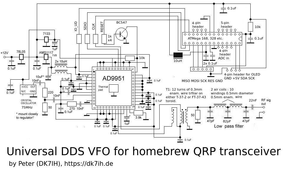
The microcontroller only is wired to the minimum. All pins that are not occupied by the DDS chip are lead to head strips so that they are accessible to the user’s own design. Software is available for 3 types of display on request:
- OLED 132×64
- Nokia 5110
- DOT-Matrix 162
- ST7735 (colored)
- ILI 9341 (colored)
If you purchase the board you will a software adapted to your needs for free (if effort to fit the code to your needs keeps in reasonable boundaries…)
Clocking
The AD9951 is capable to process input clock rates of up to 400MHz. If no such clock oscillator is available, the software contains a clock multiplier code sequence. In the VFO presented here, a 75MHz oscillator is used to clock the DDS chip by factor 4 which results in a 300MHz clock rate. Thus 60MHz output frequency in this configuration are more or less “piece of cake”.
Hardware
The PCB sizes 7 by 5 centimeters (1.96 by 2.7 Inches). The TQFP64 package is put onto a breakout board, to make construction of this oscillator possible for amateurs who do not want to assemble SMD boards.
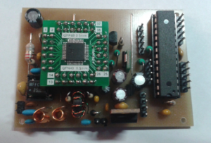
The +12V DC input is located close to the 5V-regualtor visible at the bottom. All required voltages are generated internally from the DC input. Signal output is on the left bottom corner after the low-pass filter.
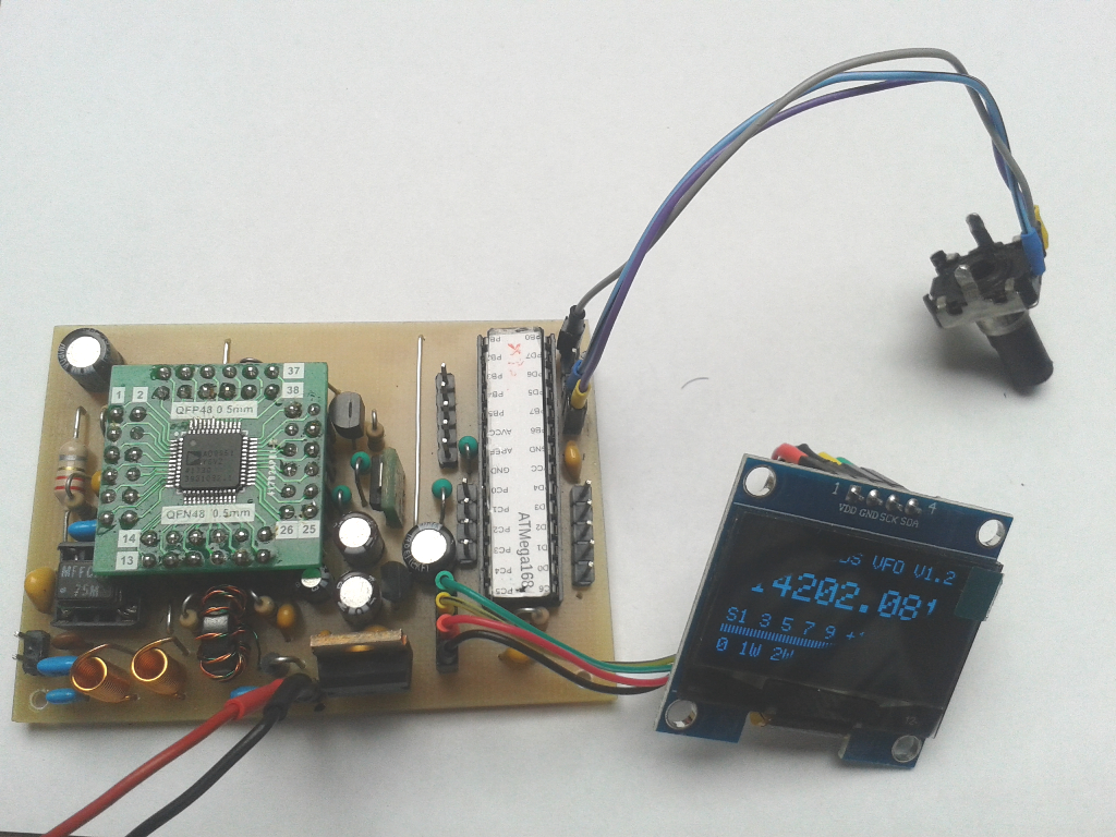
Basic application
In a basic application this module can be used as a VFO for a monoband transceiver for example. For amateurs who purchase this module the code will be supplied for free. For more convenience or multiband operation this code can easily be adapted. A respective version currently is under construction.
The basic setup is fairly simple: A rotary encoder is connected to pins PB6 and PB7 and the OLED is wired to the OLED port integrated into the module. (The strange OLED display image originates from the OLED refresh rate in contrast to exposure time of my smartphone camera.)
Performance
This AD9951 DDS VFO produces a clean output sine waveform with about 500mVpp amplitude. The loss of gain over the frequency span of about 60MHz is negligible. The video shows the oscillator connected to a spectrum analyzer running from 5 to 60MHz:
Thanks for watching and vy 73 de Peter!