Abstract
The Si5351 is widely known in the amateur community. Basically being a clock generator for digital applications it often is used as a universal variable frequency oscillator. This project shows how it can be used as a universal VFO for a wide frequency range and various external circuitry which makes it very usable in ham radio projects like transceivers, particularly for multiband application.
The VFO can produce up to 3 independent frequencies in the range from 8kHz to 160MHz. Output voltage is in the range of 3Vpp. The waveform is, as known, square wave.
Schematic
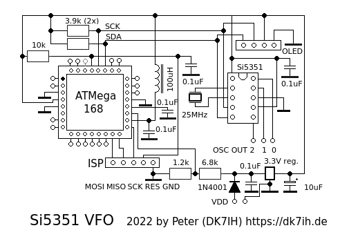
The circuit consists of 2 major parts:
- ATMega168 microcontroller (MCU)
- Si5351 clock oscillator (10-pin package)
Most of the MCU’s I/O-pins are accessible for versatile usage by the user. This also is valid for the ADC-pins that can process analog signals, like S-meters, power meter, battery voltage or temperature. ADC6 already is connect to VDD by papplying a a voltage divider to be used as a voltage meter.
Only PC4 (SDA) and PC5 (SCK) are assigned for the I²C bus. But they are also accessible, e. g. for the OLED that is intended to be used as display here.

VDD can be set in the range between 5 and 12V. The 3 outputs (OSC0, OSC1, and OSC 2) are designed for connecting a shielded cable.
Setup
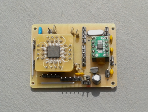
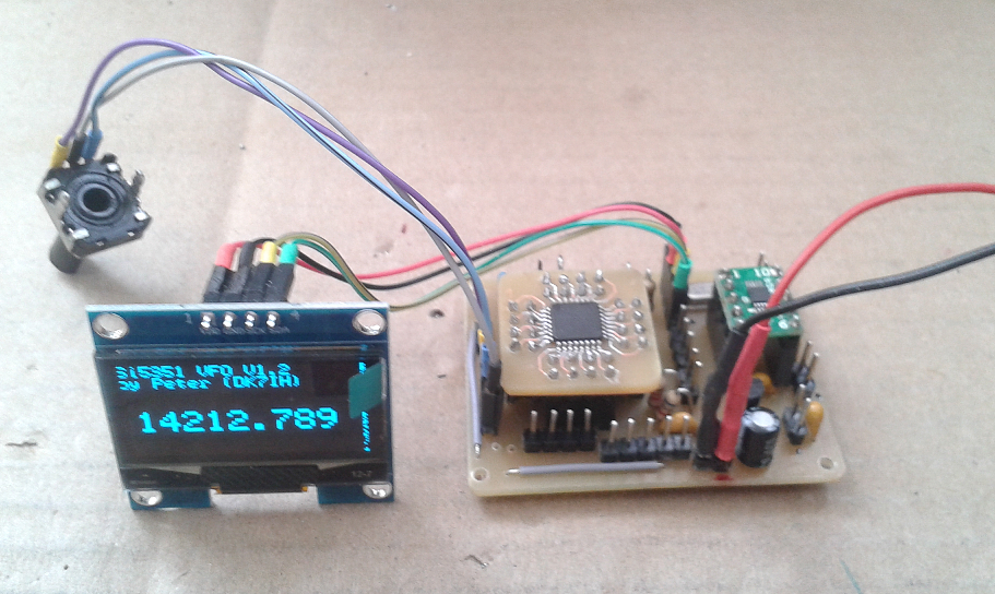
Here the final assembly of this PCB:

The board sizes about 5 by 4 centimeters (2 by 1.5 Inches). All ICs have been put on break-out boards to make assembly easier compared to SMD soldering. The ATMega168 (ATMega88, ATmega328 or whatever used) has been put onto a self-designed breakout-board also to save space compared to the 28-pin DIL version.
A PCB, a kit or a ready-to-use module are available on my QRP-Shop site. as well as the semiconductors pre-soldered to breakout-boards.
Software
A simple basic software is available on my Github account. It has been designed for being used together with an SH1106 OLED and a rotary encoder. This minimum configuration supplies the very basic functions for applying this VFO in a radio. The OLED is connected to the onboard pin header (see schematic) and the rotary encoder goes to pins PB6 and PB7 on the MCU.

Thanks for reading es 73! de Peter (DK7IH)