For a transceiver I wanted to design a temperature control for the final amplifier transistors. I have some KTY81-210 temperature sensors here in my junk box. So, one of these should be used. The transceiver again holds digital equipment (AD9951 as VFO and AD9834 as LO) driven by an AVR ATMega32 microcontroller. One of the ADC inputs of this device was designated to process the data delivered by the temp sensor.
Some theory in advance: How does a temperature sensor work?
The KTY81-210 is a “PTC” element. This to say that electrical resistance increases with temperature.
PTCs are mostly made from barium titanate (BaTiO3). This material has an interesting feature: Below the so called “Curie temperature” the material holds an NTC characteristic. Above this point the material changes its behavior and increases resistance sharply and resistance from now on increases with temperature.
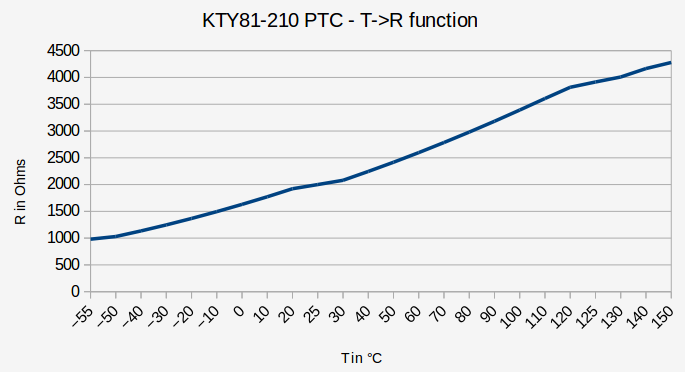
The T->R function shows a relatively linear approach with some limitations:

For the accuracy in a simple temperature measurement for PA transistors this should be sufficient.
Connecting the PTC to the microcontroller
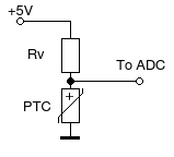
A simple voltage divider to GND is the best idea to get a voltage depending on the conductivity of the sensor element.

One thing should be kept in mind: When current flows through the sensor, the sensor will heat up. If the current is too high this will corrupt your temperature reading. Thus I recommend having Rv > 5 kΩ.
Setting up the ADC (analog digital converter)
AVR microcontrollers have a 10-bit analog digital converter (ADC) operating on the successive approximation principle. The resolution due to the number of bits used is limited to 1024 discrete values (ADC value in the range 0..1023). They can be operated with a reference voltage of either 5V or 2.56V determined by software setup.
Before you can take a measurement the ADC must be set up. This can be done in the function that is used to read an ADC value or at the beginning of the program before enterin the main() loop. I here use the complete setup in the called function (code for ATmega32):
//Read ADC value
int get_adc(int adc_channel)
{
    int adc_val = 0;

    //ADC config and ADC init
    ADCSRA = (1<<ADEN) | (1<<ADPS2) | (1<<ADPS1); //Activate ADC, Prescaler=64

    ADMUX = (1<<REFS0) + adc_channel; //Read ADC channel with Vref=VCC

    _delay_ms(3);

    ADCSRA |= (1<<ADSC);
    while(ADCSRA & (1<<ADSC));
    _delay_ms(3);

    ADCSRA |= (1<<ADSC);
    while(ADCSRA & (1<<ADSC));

    adc_val = ADCL;
    adc_val += ADCH * 256;

    ADCSRA &= ~(1<<ADEN); //Deactivate ADC

    return adc_val;
}
With this the ADC references an input voltage set to 5V.
Calculating the ADC value
The ADC value depend on the input voltage: 0 represents 0 volts, 1023 represents 5V. Any value in between is calculated by:
Vx / 5V = ADC / 1024
where Vx is the applied voltage to the ADC input channel, ADC is the figure between 0 and 1023 representing the voltage.
So, Vx equals to
Vx = ADC * 5V / 1024
Calculating the temperature from the ADC voltage
The voltage divider equation lets us deduce the value of RPTC:
5V / UADC = (Rv + RPTC) / RPTC.
which equals to
5V / UADC = Rv / RPTC + 1
5V / UADC – 1 = Rv / RPTC
(5V / UADC – 1) / Rv = 1 / RPTC
Rv / (5V / UADC – 1) = RPTC (where UADC != 0)
Once having calculated RPTC we can calculate the temperature. Therefore we assume a linear dependency of the resistor to temperature:
R = T * m + R0.
(m is the slope factor (gradient), T0 is the constant term, in this case the PTC’s resistance at 0°C).
Changing the equation so that T is the result, we get:
(R – R0) / m = T.
R0 from the datasheet is 1630Ω typical. The slope factor (gradient) can also be deduced from the data sheet. It is
m = Δy/Δx.
So we can take two points out of the function (e . g. 0°C and 100°C) and calculate
m = Δy/Δx = 100K / (3392Ω-1630Ω) =100K / 1762Ω = 0.0567K/Ω
That means that the PTC element equals a change in resistance by 1Ω when the temperature changes by 0.0567K.
Packing all this into a C-function for the microcontroller we get:
//Measure temperature of final amplifier
//Sensor = KTY81-210
int get_temp(void)
{
    double temp;
    double rt, rv = 5100, ut;
    double r0 = 1630; //Resistance of temperature sensor at 0°C
    double m = 17.62; //slope of temperature sensor in Ohms/K

    //Calculate voltage from ADC value
    ut = (double)get_adc(4) * 5 / 1024;

    //Calculate thermal resistor value from ADC voltage ut
    rt = rv / (5 / ut - 1);

    //Calculate temperature from rt
    temp = 10 * ((rt - r0) / m);

    return (int)(temp);
}
Rv of the voltage divider in this case is set to 5100Ω. For other values please change value in the definitions section.
get_adc(4) is the function to get an ADC reading (see above!), in this case the voltage divider is connected to ADC4 input.
By the way: The functions returns a 10 fold value because in the reading I add a decimal to get one tenth resolution.
73 de Peter
(DK7IH)