This VFO can be used preferably in a monoband transceiver for 3.5 or 14MHz together with an interfrequency (IF) of about 9MHz or so. The oscillator stage is a Colpitts circuit. The inductance L consists of 60 turns of 0.1mm enameled wire on an T37-2 iron powder core. C is a tuning capacitor ranging up to 20pF (surplus stuff or homemade).
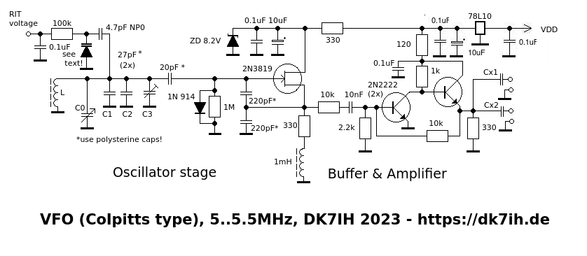
To ensure maximum frequency stability and low frequency drift the use of polystyrene and NP0 capacitors where indicated in the schematic is mandatory. Or, to say it in short, all frequency determining components should be of these types of capacitors.
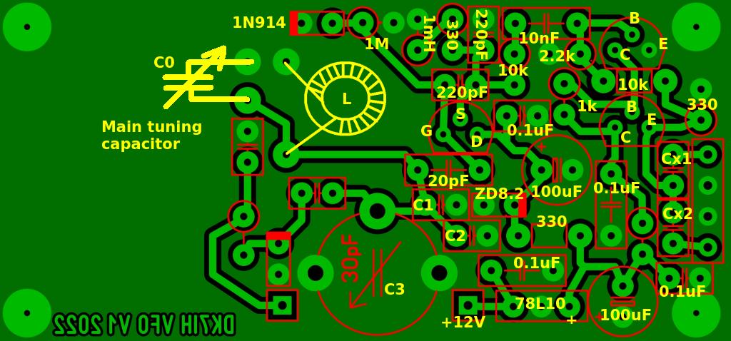
The main inductance coil (L) should be glued to the PCB to avoid mechanical stress and undesired movements which can affect the output frequency severely.
The circuit provides two output ports with individually rated capacitors to ensure proper level adjustment for the following stages.
The PCB layout (45 x 27 millimeters):
Output voltage can be expected in the range between 3 to 4 Vpp. When correctly assembled and shielded this VFO provides a stable frequency in the range of +/- 50Hz/h after a warm-up phase of about 10 minutes.