0. Abstract
This article describes an amateur SSB radio for the 14MHz frequency band that has been assembled mainly with commonly available electronic part. Particularly the use of integrated circuits (ICs) has been avoided. Some RF-related parts have been purchased on the second hand market or directly from vendors who are specialized in RF circuits like box73.de. The design objective was to create a fully operational radio with great performance that can be built mostly of commonly available and low complexity components. That lead to the acronym “SCR” = “Simple and Compact Radio”.
One of the reasons to re-think designs of analog radios has been, for example, that certain ICs are not longer available as many of these parts have been discontinued the recent years (NE612, SL6440 etc.). Other parts can be replaced as well but this approach has not been followed to the full extent so far and might be a topic for later designs.
The ambition to cope with potential shortness in components requires some new onsets when building simple but effective analog radios when you are an enthusiastic amateur.
In this project the author focused primarily on replacement strategies for integrated circuits. The semiconductors used for this project are mainly standard BJT devices like the BC547 that can be substituted by an 2N2222 for example. In the power stages of the radio frequency amplifier we find also BJTs that can be purchased by eleflow.tech, a supplier that has specialized in manufacturing the models formerly produced by Mitsubishi Japan. Or they can be pulled from old CB radios, widely available on the second hand market.
The concept uses one interfrequency (9MHz with commercial filter available from box73.de), a transistorized receiver front end, two cascode IF amplifiers and an audio section equipped also exclusively with bipolar transistors.
Particularly the mixers circuits, which formerly have been set up using ICs, have been exchanged by either diode ring mixers (double respectively single balanced) or a differential amplifier with discrete components. The latter are, more or less, an attempt to rebuild the famous CA3028A IC from RCA that has been used in a large number of QRP construictions and was discontinued in the 1990s. There are also several hints on the web to rebuild this IC (Link1, Link 2)
1. General
This radio consists of about 20 different building blocks on small units of PCB material. Each block has got an individual number that identifies the unit. Please note that the numbering is not 100% consecutive as there are modules that were developed but not were not finally used when the radio was built.
In the respective schematic of each module connections to corresponding modules are clearly marked to make it easier for the builder to establish the correct interconnections. These are done by standard hookup wire for DC lines and shielded cable for AF and RF lines. For short RF or AF connections between modules twisted wire (max. 1 to 2 centimeters in length) is sufficient.
The block diagrams of receiver and transmitter:
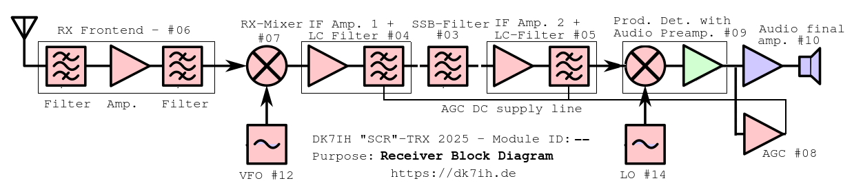
![]()
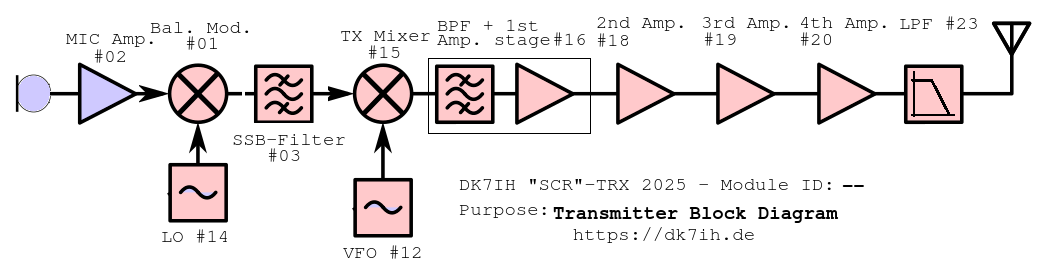
The two oscillators (VFO and LO) are shared between transmitter and receiver as well as the SSB-filter. For the ladder a signal relay has been installed to separate signals when on receive respectively transmit mode.
Coils are made of TOKO coil formers which are widely available in old CB-radios that can be purchased on the second-hand market.
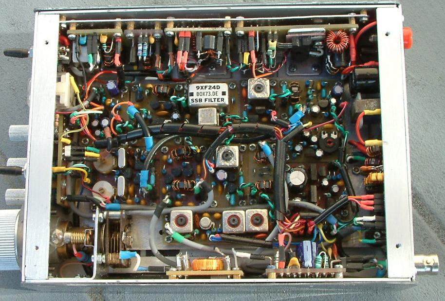
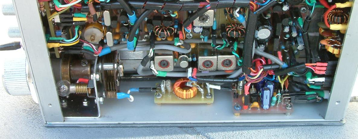
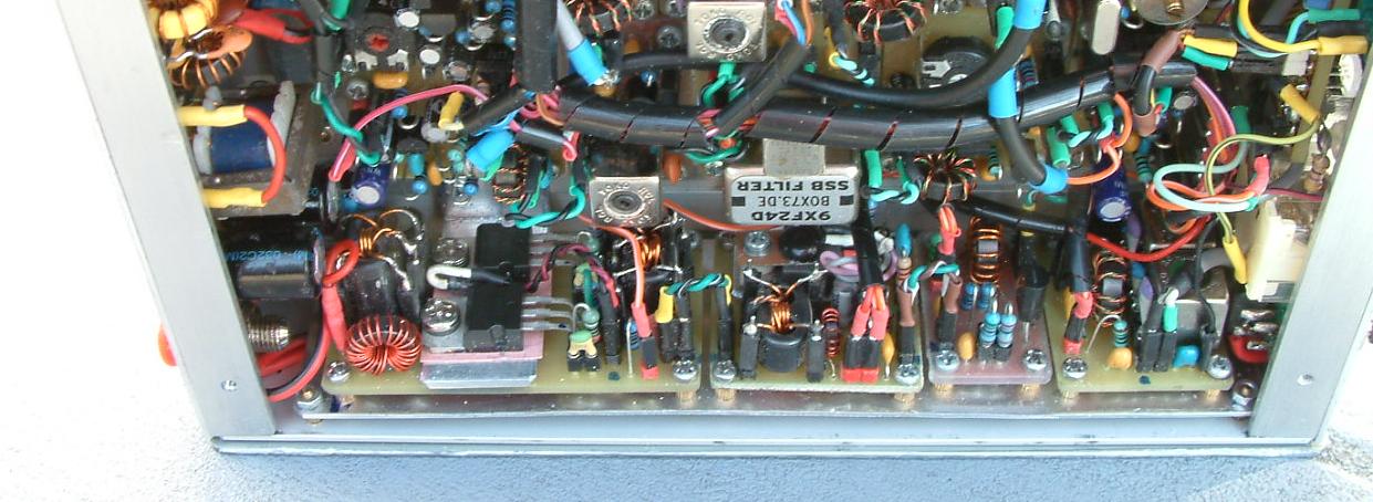
Inside the cabinet:
2. Radio circuitry
2.1 The Oscillators
2.1.1 The VFO
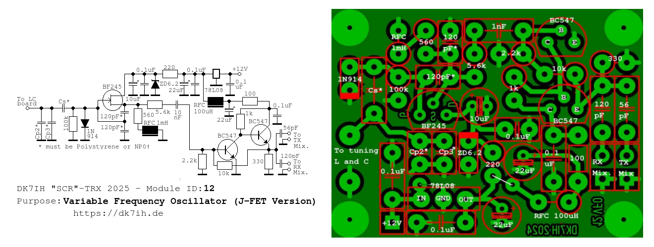
The VFO is a Colpitts layout. Frequency range is 5000kHz to 5350kHz.
On the left side of the schematic there is the input for the tuning element which has not been installed on this board. So, different tuning elements can be applied (E.g. a coil with variable C or a Varicap diode). The main oscillator uses a J-FET (BF245) which drives a two-stage directly coupled radio frequency amplifier (cascade type) equipped with bipolar transistors. Output level is relatively high (about 3Vpp.), thus small capacitors (120pF and 56pF) have been installed to reduce signal level to a suitable value for the following mixer stages.
The main tuning elements have been positioned on a separate PCB:
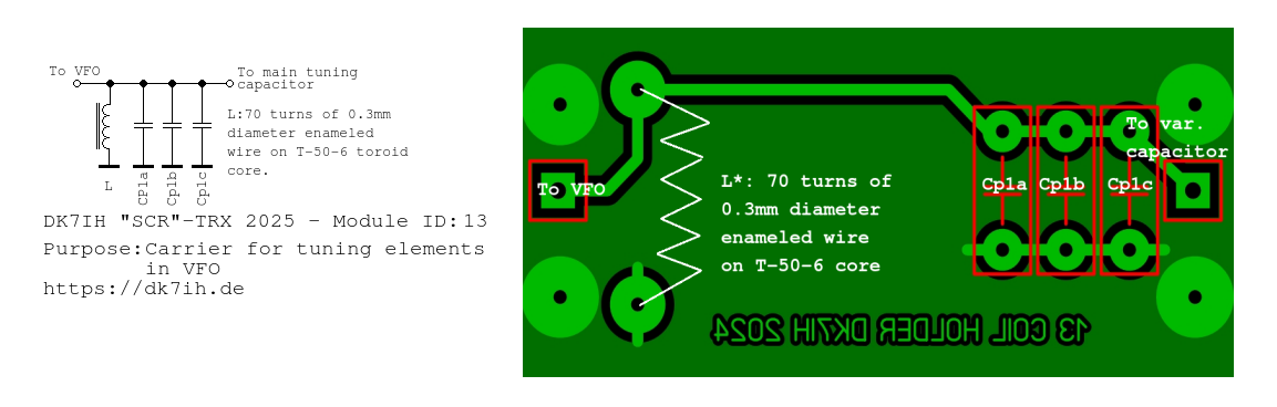
The main tuning capacitor should be equipped with a Vernier reduction drive (about 1:6 is recommended) and might be placed near the front panel.
Frequency stability considerations: To ensure maximum stability in the generated frequency, it is recommended to use Polystyrene capacitors were marked (*) in the schematic. Cs* is about 100pF whereas Cp2 and Cp3 should be selected to find the correct output frequency. Additional capacitors might be installed on the “L and C” board (Cp1a, Cp1b, Cp1c) which also should be of the Polystyrene type. Frequency drift with all these design recommendations carefully observed is within the range of some 10 Hertz over a period of 1 hour.
VFO section mounted vertically to the left side of the cabinet:
2.1.2 The Local Oscillator (LO)
The Local Oscillator (LO) also uses the Colpitts design:
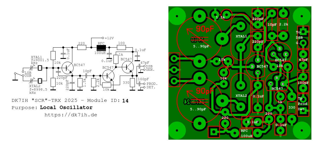
For the 9-MHz-SSB-Filter suiting crystals are available from box73.de. With a 5..90pF trimmer in series they are tuned to the exact sideband frequency. The oscillator should be placed close to the front panel to keep sideband switch leads short.
2.2 The Receiver
2.2.1 Front End, RX Amplifier
The first amplifier stage in the receiver section is based on a bipolar transistor amplifier. As for the other RF stages in this radio the BC547 has been used. Builders from outside Europe might prefer the 2N2222 device which also is common in homemade radios. In addition the author has developed the same module with a Dual-Gate-MOSFET, that can be seen on the photos. Both modules perform more or less the same, but the latter version is part of the AGC chain which the bipolar version is not. Here we refer to the BJT version.
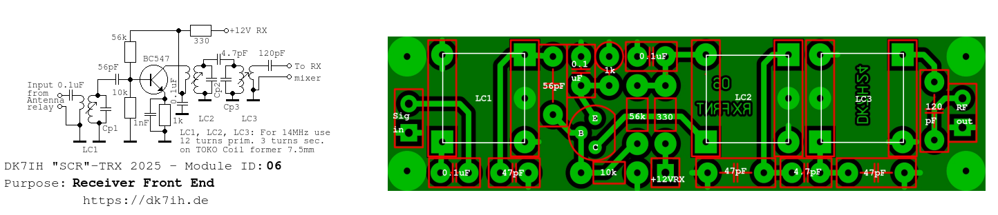
Preselection is achieved using LC1 as tuned circuit for 14MHz. The coil is wound on a 10mm TOKO coil former from old CB radio transceivers. Winding data: Primary: 12 turns, secondary 3 turns. Parallel capacitor is in the range of 47 pF für 14MHz.
The following amplifier stage uses grounded emitter to achieve high signal gain. After amplification the signal is filtered again by a two staged band filter with the same coil and capacitor data like LC1. As the following mixer stage is very resistant towards high input input voltage this stage has not been included into the AGC chain. This front end proved to be very selective.
2.2.2 RX Mixer
The next stage is the RX mixer. From experience we know that diode ring mixers offer excellent performance concerning IMD problems with high signal levels.
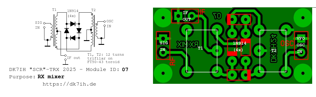
Diodes can be either 1N914 or Schottky type ones like the BAT41. T1 and T2 are wound on either a FT-37-43 or FT-50-43 core, depending on availability. There are 12 turns trifilar with 2 windings connected to form one winding and the remaining 3rd as the other winding.
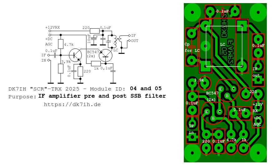
2.2.3 IF Amplifier I
Diode ring mixer generate a certain loss (about 6dB) in signal gain. Therefore a two staged cascode interfrequency (IF) amplifier has been designed to level up the signal before it will pass the SSB filter:
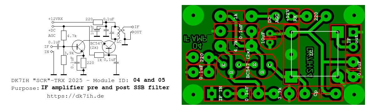
The cascode amplifier offers high gain and can be controlled by the AGC chain by setting the bias voltage appropriate to the designed gain. The difference between a cascade and a cascode amplifier is that in the cascade version the first transistor’s collector (common emitter stage) connects to the base of the second (also common emitter stage) whereas the cascode type’s 1st transistor (common emitter stage) connects to the emitter of the following transistor (common base stage).
LC1 ist tuned to the interfrequency of 9MHz. With the TOKO 10mm coil former earlier mentioned and 12 turns primary (3 turns secondary) the parallel capacitor should be set to 100 to 120 pF to achieve a frequency of 9MHz.
2.2.4 SSB Filter
The SSB-Filter PCB is shared between the receiver and the transmitter section.
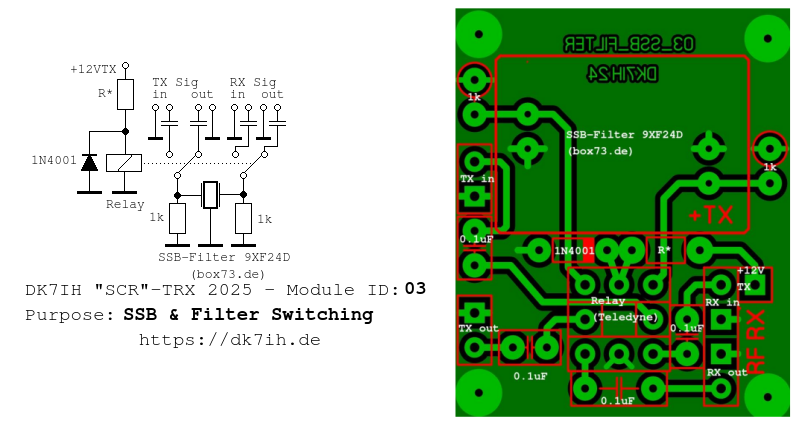
A Teledyne high quality signal relay type 172-5 has been used for this. These relays are very expensive (about 50€ per unit) but are sold second hand for about 10€ on ebay etc. As the coil voltage rating is 5V a resistor (R*) of 820Ω has been built in to protect the coil from excessive current. A clamp diode protects the rest of the DC circuit from excess voltage when the relay is switched of and according to Lenz’ law reverse voltage is induced into the DC line.
The SSB-Filter is, as mentioned before, a commercial device purchased from German supplier box73.de. The SBB-Filter terminates with roughly 900Ω according to datasheet. Thus there is a 1kΩ resistor connected in parallel to the filter leads. There is also a capacitance of some picofarads mentioned in datasheet, but this has been ignored due to practical reasons..
2.2.5 IF Amplifier II
This stage has the same circuit like interfrequency amplifier #1. But the board layout slightly differs because of the needs of the author’s special installation into the cabinet.
2.2.6 Product Detector & Audio Preamplifier
The product detector in this radio also is a diode mixer type. Due to simplification a design with only 2 diodes has been used. Thus we have a single balanced mixer. Theoretically this goes along with reduced carrier suppression and decoupling of the various ports which does not cause significant problems when the resulting frequency is in the audio range:
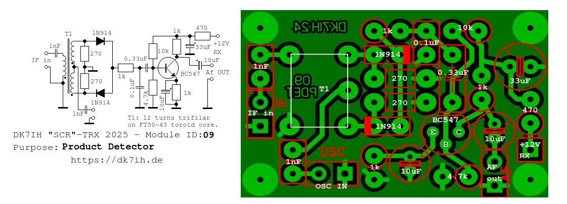
T1 is of the same like the other broadband transformers covered so far: 12 turns trifilar on either a FT-50-43 or FT-37-43 toroid core. LO signal is fed into the 1nF capacitor.
The 1kΩ resistor at the mixer’s output plus the subsequent 0.1uF capacitor form a low pass filter to eliminate remaining radio frequency as well as to reduce hiss noise in the audio spectrum and make listering more pleasant. The following audio stage in common emitter circuit gives about 20dB of gain to the audio signal.
2.2.7 Audio Final Amp
The receiver’s last module is the audio power amp. Here we find a push-pull-design with a pair of NPN and PNP transistors.
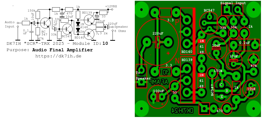
The first two stages work as voltage amplifiers providing enough drive voltage for the last stage in push-pull mode that serves as a current amplifier. The two 3.3Ω resistors connecting to the loudspeaker are for current limiting purposes and provide some sort of emitter degeneration to get more linearity from the output stage and protect from overheating. Output power is about 1 watt with a speaker of 8Ω impedance.
2.2.8 Automatic Gain Control
AGC control voltage is audio-derived.
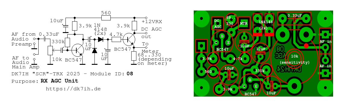
On the one hand this board provides a feed-through for the audio signal go to the volume potentiometer on board #11 (“AF”). But the main purpose is to produce a DC voltage reversely depending on the audio input signal. This DC voltage then controls interfrequency amplifiers 1 and 2 and sets their gain to appropriate levels depending on incoming signal strength.
A first audio amplifier produces an audio voltage in the range of 2 volts max. This is rectified and fed into the second stage that, after a loading capacitor defining the “hold” time and the decay is formed by the second transistor. The voltage drop in the emitter line is used to set the S-meter in the front panel. The collector voltage drop supplies the AGC voltage for the interfrequency amplifiers. The first stage has been decoupled thoroughly concerning the DC line from the rest of the circuit to avoid any unwanted side effects that might lead to improper dc regulating behavior like “plops” when the radio goes from receive to transmit mode or vice versa.
2.3 The Transmitter
2.3.1 Microphone Amplifier
The first stage of the transmitter is the microphone amplifier:
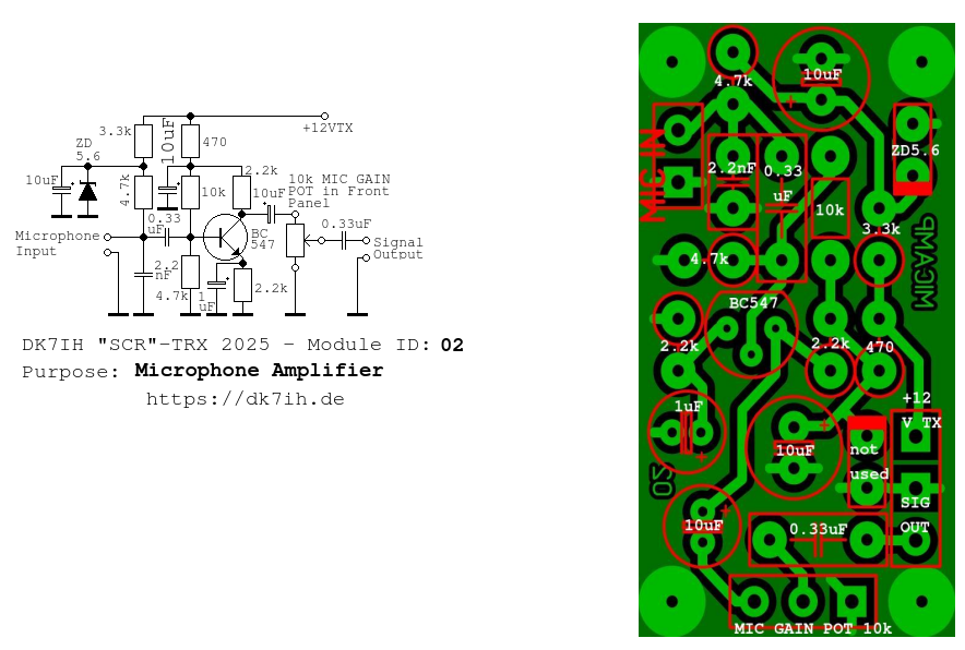
This amplifier stage is for use also with an electret microphone which is recommended. A network made by two resistors (3.3kΩ and 4.7kΩ), a Zener diode and a filtering capacitor (10uF) provide the respective voltage for the built-in amplifier stage in the electret capsule. Amplifier gain has been set to the characteristics of this microphone type. The design again is common emitter with a 1uF coupling capacitor to GND. A gain set variable resistor in the front panel should be connected to set microphone gain properly. Thus it is recommended to put this PCB close to the front and to use shielded cable to protect the circuit from unwanted coupling of stray radiofrequency energy which might lead to a distorted audio signal.
2.3.2 DSB Generator
The DSB mixer is an active device. A differential amplifier with a current source has been set up. This is more or less a reconstruction of the famous “CA3028A” IC that could be found in many QRP constructions of the 1980s and 90s.
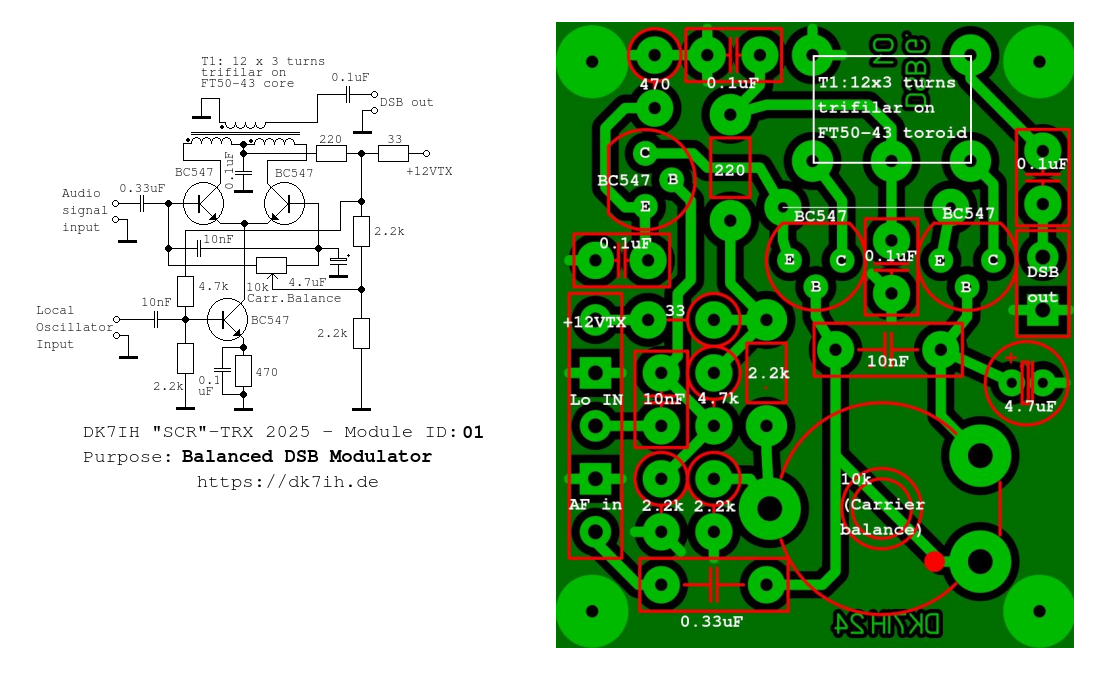
The differential amplifier basically has 2 inputs that go to each of the bases of the top positioned two transistors.
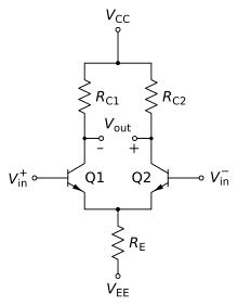
The device amplifies the voltage difference between these two input by a certain amount of gain. Vout = A(Vin+-Vin-) where A stands for the individual gain of the device. In addition a current source is formed by the third transistor. When we tie the inputs together and use them as one input (for the signal) and apply the oscillator to the current source, we get a balanced mixer. Optimized carrier suppression can be achieved by balancing DC bias voltage between the bases of the differential amplifier transistors.
Carrier suppression is excellent and in the range of about 50+dB. A trifilar transformer picks up the signal from the collectors and hands that over to the next stage which is the SSB-Filter (see above!)
2.3.3 TX Mixer & 1st RF Amplifier
The transmit mixer also is a differential amplifier with current source.
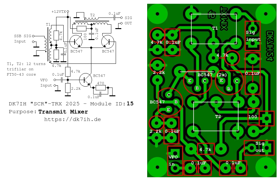
The 9MHz-SSB signal is fed symmetrical into the differential amplifier as the current source again is fed with the oscillator signal, in this case from the VFO. T1 is center tapped. This provides a radio frequency signal appearing with 180° phase shift to the bases, so we get high amplification gain. This is superposed by the VFO signal in the current source so that a high level of output signal can be achieved.
2.3.4 1st RF Power Amplifier Stage
The first stage in the power amplifier leads in with a two-pole band pass filter (BPF):

LC1 and LC2 are also based on 10mm TOKO coil formers from old CB-radios. Winding data is exact the same as in all other application in this radio: Primary 12 turns, secondary 3 turns. Parallel capacitors Cp1 and Cp2 for 14MHz are 47pF. The subsequent amplifier works in common emitter mode, output level is about 20mW PEP. This equals 5Vpp. to an estimated load of 150Ω. A broadband transformer (trifilar with 3×12 turns forming the center tap by connecting 2 of the 3 windings) lowers impedance to about 50Ω (all roughly estimated). This stage operates in A-Mode due to achieve full sensitivity with small signals and optimized linearity.
2.3.5 2nd RF Amplifier (Predriver)
The second stage in the power transmitter:
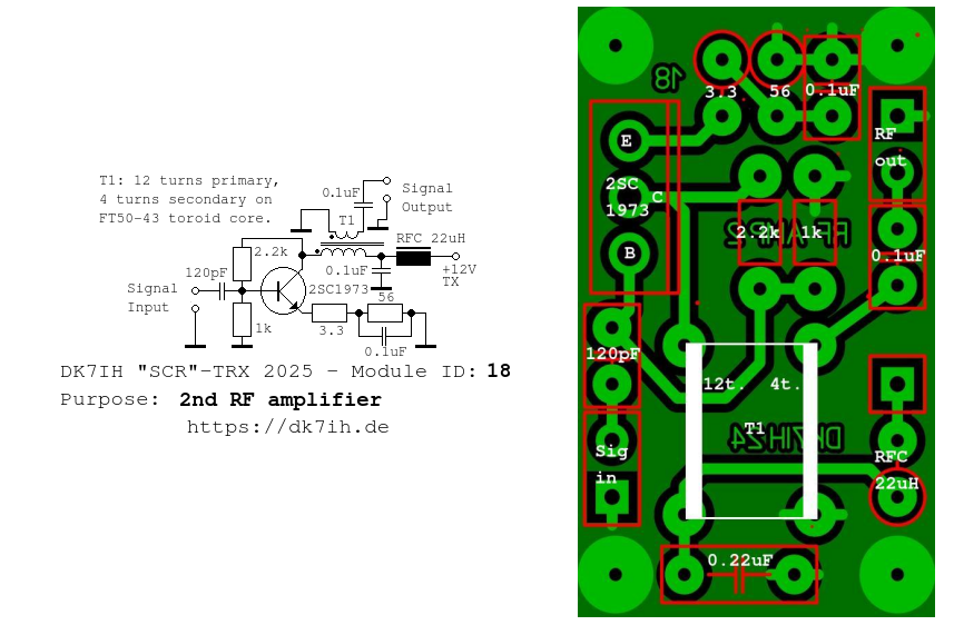
The RF power transistor in this stage is the 2SC1973 that also can be obtained by eleflow.tech or on ebay. Power level in this stage is about 200mW PEP to approx. 50Ω impedance. This stage also is biased for AB mode operation.
2.3.5 3rd RF Amplifier (Driver)
The next stage is designed to push power level to about 1 to 2 watts PEP:
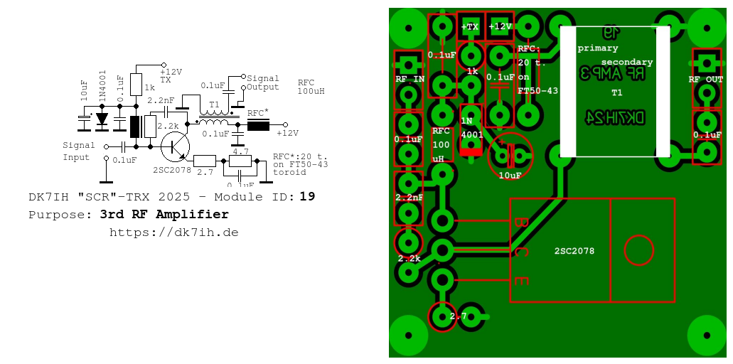
Active element hier is a 2SC2078 from eleflow.tech. The stage is biased in AB mode. Bias current is provided via the 1kΩ resistor, a decoupling network made from an 10uF electrolytic capacitor, a 0.1uF ceramic capacitor and the 1N4001 diode are designed to limit bias current to exactly the level necessary for AB-mode operation. The diode should have a thermal connection to the transistor. In case the transistors heats up, the diode also does. As electron flow in semiconductors increases with rising temperature higher current from the 1kΩ resistor and the transistor’s base is lead to GND and therefore reducing dQ/dt through the transistor’s input and subsequently limiting quiescent current. This measure above all prevents thermal runaway successfully.
A negative feedback network also has been installed to improve linearity.
T1 is a 12 turns primary and 6 turns secondary transformer on a FT-37-43 or FT-50-43 toroid core.
2.3.6 4th RF Amp (Final Stage)
This stage levels transmit power up to the range of 15 to 20 watts PEP output, depending on supply voltage. With 14.4V DC input voltage power output is approximately 20 watts.
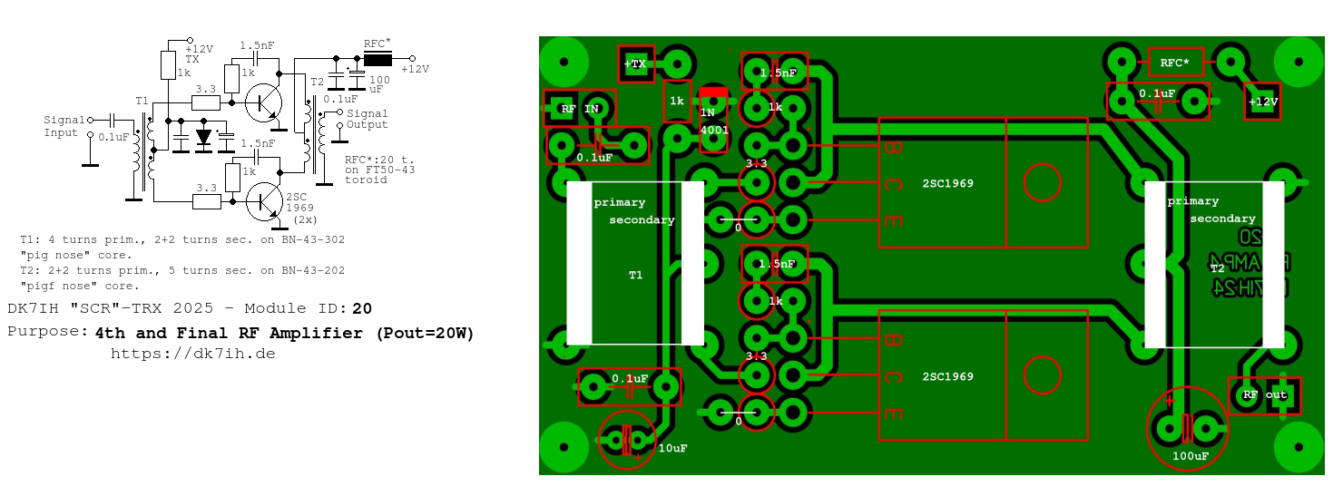
The device is in push-pull operation. So it shows improved suppression of even harmonics. The stage is biased with the same circuit like stage #3 to AB-mode. The input and the output transformer’s data is given in the schematic. Here “pig nose” cores are used. The input transformers decreases impedance from about 50Ω to about 12Ω per side. The output transformers vice versa from about 10Ω to approx. 50Ω. The semiconductors used are 2 CB-type power transistors 2SC1969 from eleflow.tech. A negative feedback network also has been installed to improve linearity.
Complete power amplifier on the left side of the cabinet (vertically mounted):
2.4 Misc Modules
2.4.1 DC Switchboard with TX Low Pass Filter
The DC switching between transmit and receive mode is done by a 5V surplus relay. The relay and the necessary connectors have been put onto a separate board together with the transmitter low pass filter for suppressing harmonics to the required degree and the power measurement unit that provides DC voltage for the meter to check transmitter output level during transmission phase.
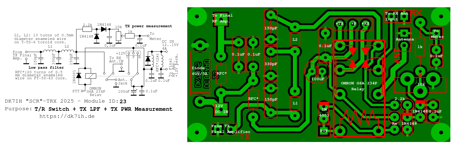
The relay in use is an OMRON 5V device from the surplus box. Thus a current limiting resistor (Rx) has been installed that must be bridged when using a 12V type of relay. In the author’s setup this resistor was set to 220Ω. Also there are DC decoupling RF chokes (RFC*). The respective data is mentioned in the schematic above.
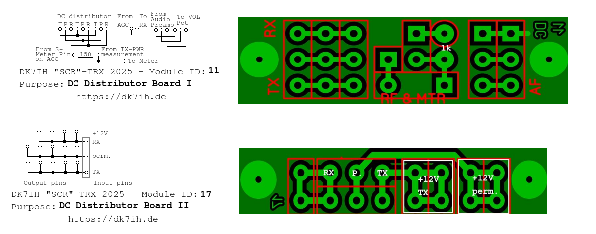
2.4.2 DC Distributor Boards
To make wiring of the radio easier there are two DC distributors in the author’s setup. They are intended to provide local power supply for transmit, receive and permanent power lines.They can be ignored in cases builders wish completely different setups in their rigs.
2.4.3 DC LPF for Final RF Amplifier
In this radio the author encountered a strange effect on the DC line. When the final amplifier was connected and output power increased above 5 watts PEP then there was a sort of coupling to the (as after long research period it turned out) microphone amp. This coupling led to unwanted signals in the TX output and was transferred via the 12V DC line active in transmit mode. Therefore a DC decoupler has been developed which fully solved the problem. The first hint came, when the effect disappeared when the final TX amplifier was connected to a different and therefore independent power supply.
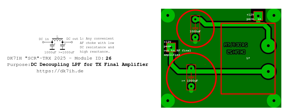
The “massive” coil (“L”) has been pulled from a surplus CB radio where these devices are present as DC filters for the final amplifiers. If such a coil is not available and it is required to manufacture an own one, it should be observed that it is made of wire of suitable diameter (0.4mm at least) and enough turns to produce as much inductance as possible.
3 Enclosure
The enclosure for this radio also is a very simple design. An aluminum rod in “L”-shape from the local hardware store had been purchased. Four pieces in appropriate length had been cut off as the side walls and then were bolted to an aluminum plate (1mm thick for enhanced rigidness) which forms the base of the radio and on which all the modules have been fixed using M2 spacers, nuts and bolts. The top cover also is an aluminum plate (0.8mm strong) with a suitable opening for the loudspeaker. This plate has been fixed with countersunk screws to improve optical appearance.
4 On the air
During the recent ARRL DX contest 2025, the author could establish contacts with several stations located on the East Coast of the USA. A dipole, approx. 12 meters above ground, was used as antenna.
On a Kiwi-Web-SDR the following output has been spotted:
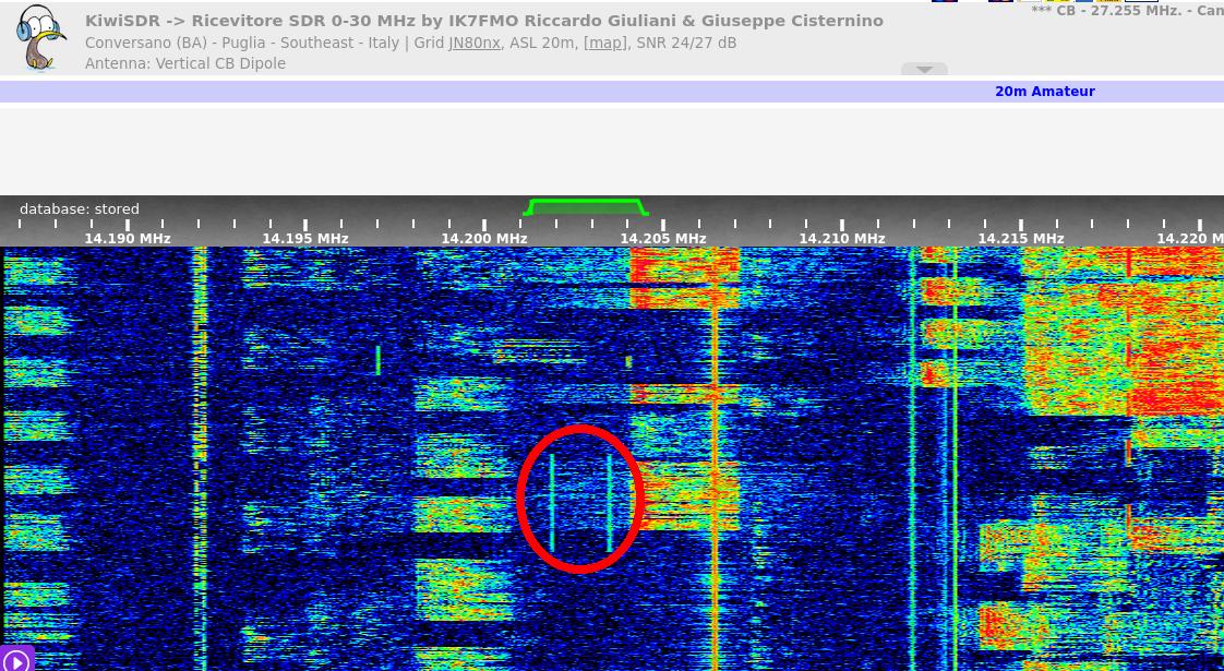
Data: Dual-Tone Input, Output power 20 Watts on approx. 14201kHz.
Thanks for reading!
Peter (DK7IH)