Ken, WA2MZE, commented on my article about the 20 Meter/14MHz QRP SSB handheld transceiver. He gave me some inpsiration to revise the AGC circuit. The older version did not include the IF-amplifier into the AGC strip. I thought a short while and then decided to reconstruct the AGC-RF-meter circuit board because for the first version there was not enough space left to include a regulator circuit for the MC1350 integrated IF amplifer.
So, here is the new circuit:
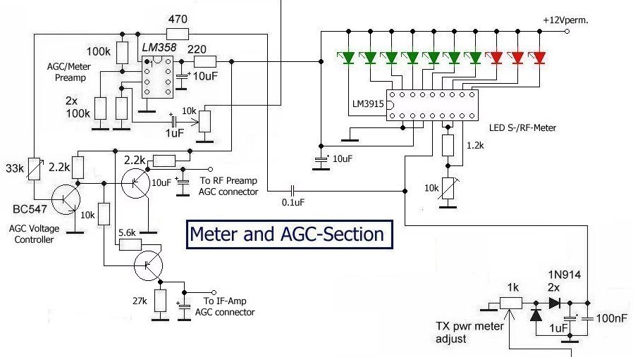
The circuit delivers 2 contrary types of regulating voltage:
The upper PNP-transistors pulls a 12V DC signal to ground. This controls the Dual-Gate MOSFET used in the rf preamp stage. The lower the gate voltage of this semiconductor, the lower its gain.
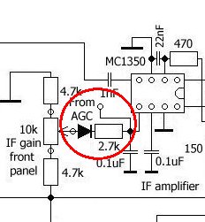
The lower PNP-transistors works vice versa. If current is lead thru the device, the emitter will gain more positive potential. This lowers the gain of the MC1350-amplifier circuit in the if stage. Thus some minor changes had to be made within the IF amplifier:
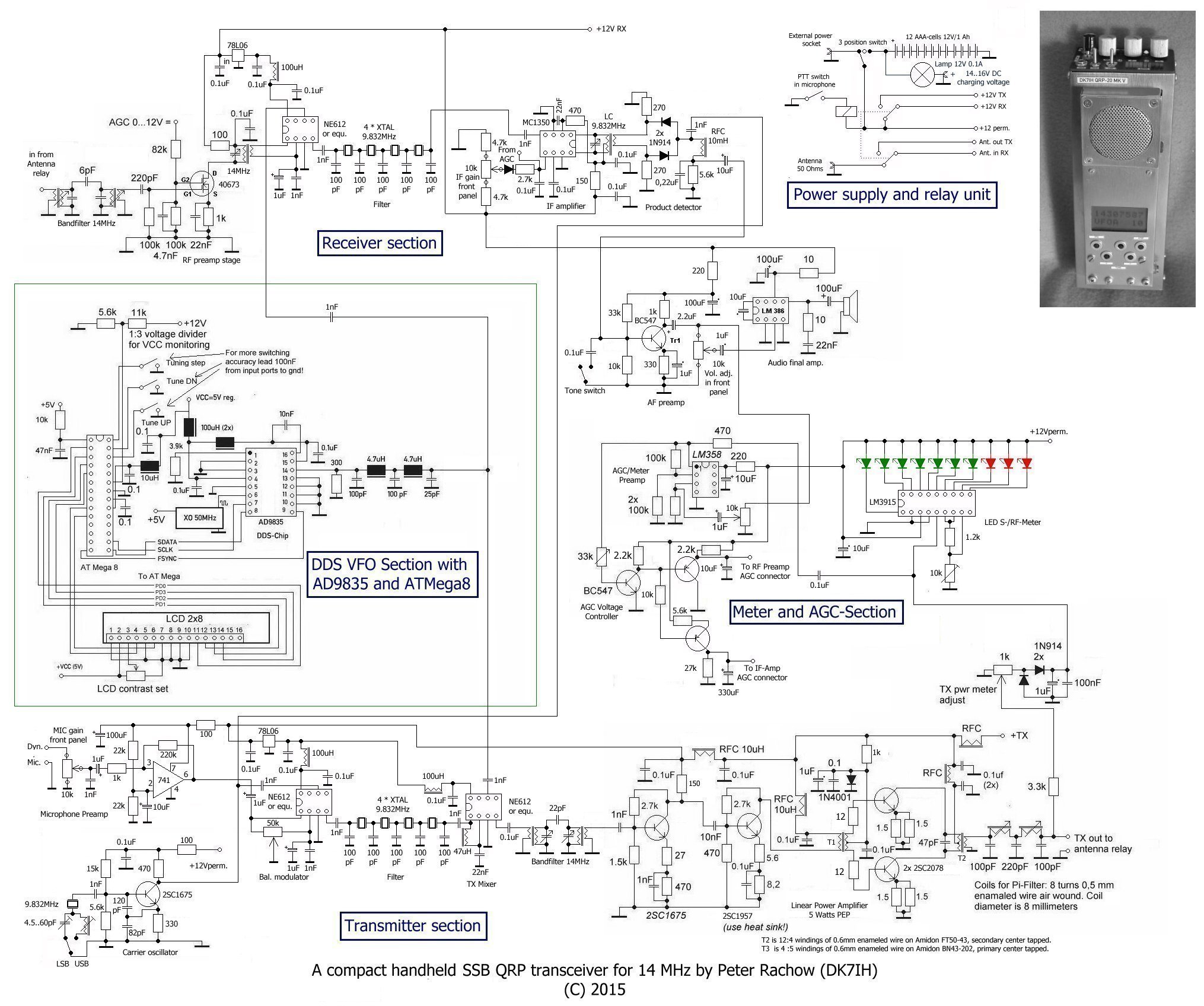
And here is the revised and completed circuit of my handheld QRP SSB transceiver for 20 Meter / 14MHz:
Result: Dynamic range has been greatly improved. Even extremely strong signals can be processed automatically without the need to manually adjust the volume control.
TNX to Ken, WA2MZE, for making his annotations! 73 to all!
Peter
Nice work with only a few extra parts!
I guess if you don’t have any really strong stations nearby on the 20 mtr band the ‘612 will behave. I’m thinking of building my own version of your designs, but I’ll probably use a separate MCL mixer and keep the ‘612 for just the TX mixer. Also I have a 10.7mhz filter from an old CB rig, that IF frequency will enable me to do a band image for both 40 and 20 with one VFO range (though with DDS it’s really just software!).
BTW I like the way you’ve added the carrier null to the ‘612 circuit.
Nice work!
If I modify the mixer to SBL-1, add bipolar 2N5109 as RF amplifier(No age) and add a IF pre amfilier using dual gates mosfet and feed the AGC to G1, Is it a good idea?
Hi Hsu,
from the general point-of-you I think you are right. That should work. But I would feed the AGC voltage always to G2 of the dual-gate MOSFET. I have sometimes seen circuits when they use G1 as gain control input but according to my own experiments I found that maximum gain of the amplifier that you can achieve with G1 as AGC voltage input is clearly behind the version with G1 as signal input and G2 as AGC input.
Vy 73 de Peter (DK7IH)