This is just to illustrate the technical description of my 5 band QRP SSB transceiver with a little more material. I took some pictures of the final assembly of the rig. This is how it looks when put into the cabinet:

The front panel labelling is made with a text processor painting the text on a piece of grey paper. After this has been printed the labels are cut out and covered with adhesive tape. The tape is slightly larger than the piece of paper so that it can be used to fix the label to the front panel.
The cabinet is bent of 2 halves of 0.5 mm aluminium sheet metal joint by bolt connectors. As I mentioned before, to keep the rig neat in size I’ve used a sandwich construction that you can see underneath. The transmitter board is on top,
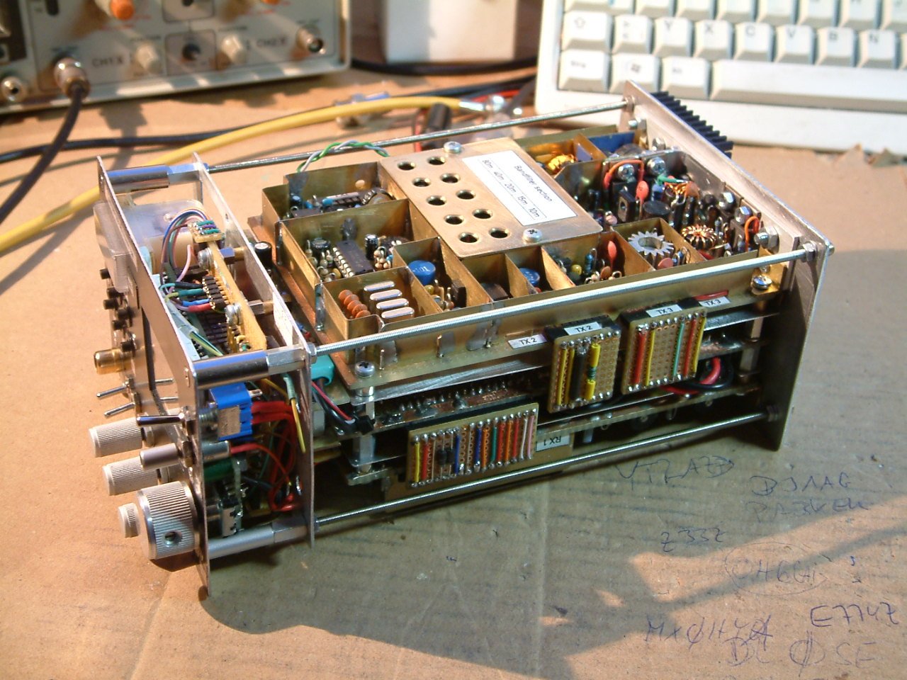
the switching board with relays and output low pass filters is centered and the receiver board is sited at the bottom:

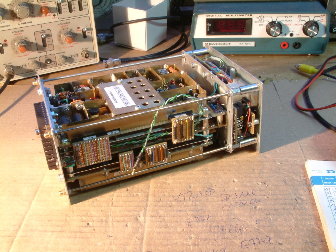
To make the construction more rigid I’ve inserted 4 threaded bars from the front panel to the rear plate:

The heat sink is from an old PC where it was used to cool the processor.
The front is a separate unit which holds the microcontroller, the colored display and the DDS unit. This VFO can be seen on the right on the next photo:
So, that’s all so far from the story… 😉
vy 73 de Peter
Peter, I wrote before for 5 band rig, about dds amplifier and said that not amplifies enaugh. By the way, “i can interest the rig sometimes, for a few day per month. ”
You remember, on my rig, when i connect the emiter of transistor to the ground, transistor amplify fully.
But that was wrong way.
The transistor was heating.
So i try some ways.
When i changed emitor resistor parallel capacitor which is 1nf to 10nf, transistor amplify fully.
Now, my receiver is perfect. No question about it.
Hello Dündar Yasa,
yes, I remember. It was the DDS amp that caused problems. IIRC I used 100nF for that (have to look at the schematic again!).1nF is too low. Nice to hear that it finally works!:-)
vy 73 de Peter (DK7IH)
Hola buenos días, quería saber si puedo conseguir los circuitos, gracias Pablo LU8JFJ
Hola Pablo! Los circuitios aqui:
https://dk7ih.de/gimme-five-a-qrp-ssb-transceiver-for-5-bands-with-10-watts-output-power/
La página de inicio está es dk7ih.de (con todos los demás circuitos).
Saludos! 🙂 Peter (DK7IH)