Abstract
An SSB radio for the HF bands will be presented. Featuring 12 to 20 Watts of output power (depending on DC supply), full DDS frequency generation, covering 6 major frequency bands (1.8, 3.5, 7, 14, 21 and 28 MHz) within the short wave amateur radio spectrum. The rig also features colored LCD and front panel backlight.
Content
- Part 1: Project Basic Outline Presentation
- Part 2: The Oscillators (VFO, LO and Testtone Osc.)
- Part 3: The Microcontroller (ATMega128)
- Part 4: Bandswitching Logical Circuits
- Part 5: Measuring Transceiver Data
- Part 6: The Receiver
- Part 7: The Transmitter
- Part 8: Transmit/Receive Switch Unit
- Part 9: Mechanical construction
Project description
In this upcoming series of articles a relatively complex project will be discussed. It is some sort of „remake“ of my last multi-band QRP SSB transceiver that has been entitled the „Gimme Five“-Transceiver and that was finished in 2015. „5“ in that case stands for the 5 major (i. e. „classical“) RF bands: 80m, 40, 20m, 15m and 10m the radio covered. This new project (called the „Midi6“, because it is not a “Micro” or a “Mini” transceiver 😉 ) covers one band more, the range has been extended to 160m.
The basic features of this construction are:
- Dual DDS frequency generation (AD9951 as VFO, AD9834 as LO),
- Colored LCD (CP11003) with resolution 240×320 pixels,
- Microcontroller ATMega128,
- Single conversion superhet receiver, interfrequency 9 MHz,
- 5 stage high quality transmitter, Pout=20W (max. at 15V DC) , featuring a microcontroller driven regulated gain stage to ensure absolute constant output on all bands,
- Integrated 2-tone oscillator for testing and tuning,
- Front panel full backlight.
“Experimental radio” means that there is enough space inside the cabinet to change boards and test new ideas in the same space. Also certain components like the SSB-filter have been made as “plug-in” components to enable quick change of the part. Also the connector between the various transmitter and receiver stages have been done by “jumpers” and header strips so that resistors and capacitors can be changed quickly to experiment with other values.
The radio has been realized with standard veroboards (0.1″ pitch), SMD components and been put into a homemade aluminum cabinet using 2 layer sandwich construction inside the cabinet.
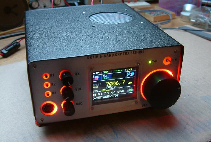
Here a snapshot of the operational transceiver. Cabinet size, by the way, is 7.5 x 16.5 x 19.5 centimeters (2.95 x 6.5 x 7.68 inches). These dimensions are in the range of other multiband QRP transceivers like the Elecraft K2 (larger) or the Icom IC703 (a bit smaller).
Stay tuned for the next article(s)!
73 de Peter (DK7IH)
Nice package! Can’t wait to see the design. Secretly, I’m hoping for something original (other than the usual MosFet RF stages), but I’m sure you’ve reused previous circuits. I’d like to play with the hybrid-cascode topology from QST myself, and yes the J310’s while long in the tooth in TO-92 package are available in SMT quite cheap, as are the 2n3904/06 bipolars. So that circuit should still be possible.
Some time ago I made a home brew enclosure for a radio project from a 1 gallon rectangular can of mineral spirits (empty of course!). I cut the top and bottom off the can with a can opener and a Dremel, and then cut the can in half the long way. What became the top and bottom of the can enclosure were then attached to a chassis, with the result somewhat resembling the Heathkit SB series units.
Hello Peter,
As usual you’ve been busy on the bench, I very much look forward to reading about this latest project. I agree that maintaining receiver and transmitter gain in a multiband transceiver is a problem that would benefit from using a uController to set stage gain. If you used a faster uController you could achieve this in real time as part of an AGC system. Let’s see what you’ve designed!
73 Paul VK3HN.
Hi Paul, I think I could add an analog ALC in parallel and use the Dual-Gate MOSFET with this one. This will be a project for later. But as the transceiver has been designed for experimenting (including leaving enough space in the cabinet for possible expansions) this might be an option. Currently I am considering adding a 100W power amplifier stage with two MRF455 transistors to have e real mid power radio. Vy 73 de Peter
Hi Peter…You reached the Zenith with this project…I am going to read it carefully while going on with the “gimme five”…My best compliments! See you!
Hi Ciro, great to hear from you again! Hope the everything is fine! vy 73 de Peter
Great!!! Well done
בתאריך יום ו׳, 3 בינו׳ 2020, 19:27, מאת Radio Engineering Projects powered by DK7IH (Peter) :
> Peter (DK7IH) posted: “In this upcoming series of articles a relatively > complex project will be discussed. It is some sort of „remake“ of my last > multi-band QRP SSB transceiver that has been entitled the „Gimme > Five“-Transceiver and that was finished in 2015. „5“ in that case s” >
It is another excitement project from you.
I’m waiting for the schematics.
If you allow us to apply your project, i want to redraw as use DIP compenents, because to use SMD is pretty hard for me. Seller sells at least 50 pieces each one. So i do not apply smd. DIP is more applicable for me.
The previous 5 band, which i apply, is working wery well.
Thank you.
Hi Dündar, thanks for the nice review. The schematics are placed in the various sections of the reports. And of course you are free to draw new board layouts if you wish! Vy 73 de Peter
Okay Peter, i see the schematics.
Thank you.
Hello Peter and congratulations for your mounts which help us well in our RC F5KEI.
In your last receiver mount I can’t get the AGC to work to the MC1350 (permanently at 12v).
Also RF Gain potentiometer has no action;
isn’t there an error on the schematic.
Thank you for your help;
73 F5ETM
Hello Jean-Pierre, with a quick check of the RX schematic I could not find any error. Does the MC1350’s gain decreas when you apply +12V DC via a 2.2k resistor to PIN5? vy 73 de Peter
Hello Peter, thank you for your response,
Here’s the change I made:
I put 5.6k on the transmitter of the PNP BC557 and replaced the 1k on the collector by 27k, put two heel resistors on each side of the 10k RF GAIN pot and now I set the AGC voltage between 4v and 6v keeping 2.7k on pin 5 of the MC1350. It’s very sensitive; from 0 to -60db in 1v ( from 5V to 6v).
Best 73 Peter, have a nice day.
Hi Jean-Pierre, thanks for the modification, will try that next time! Vy 73 de Peter
Just wanted to let you know that me and my father are building this particular transceiver based on your design with some changes by ourself. Thank you very much for your blogs! Great work!
Hello Benny! Thanks a lot and have fun when rebuildung the project. And please keep me informed about your ideas concerning changes! Vy 73 de Peter DK7IH
Good day Sir,
I read your entire article… and you convinced me to try to replicate your work…
The HAM spirit is what I re-discover a couple of months ago, a hobby that I forgot from early eighties… and I try to return to it. But a lot of things changed from that days, so I learn and discover. Your project show me a new face of that.(the HAM spirit). In the end, I will try to design several PCB’s and to build a replica(if I am allowed) of your transceiver. First of it, the receiver(I don’t have yet autorization to get in the air)…
Sincerely yours,
Dan Minciu
Hello Dan,
thanks a lot for your comment. All material here is free to use as long as there is no commercial background, e. g. producing radios form this website and selling them. This website is for scientific purposes only, as long as this is kept you can use whatever you like.
vy 73 de Peter