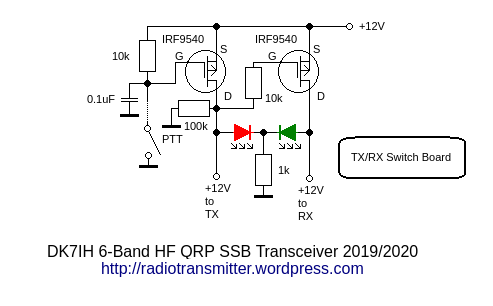
This unit is a very simple one. I did not want to use more relays than necessary. The consequence was to save at least the one commonly used in the transmit-receive switch unit. Here 2 p-channel MOSFETs do the job:

Hint: The “PTT” in the radio here leads to a PIN of the MUC switching the transmitter on. For general purposes a “PTT” has been drawn into the schematic.
Function: When Gate (G) is “hi” (i. e. close to VDD) the S/D channel goes to nearly infinite ohms. Resulting current is 0A apart from some uA leakage current.
When S is pulled to GND, or, to be more exact, some volts lower than VDD the S/D channels switches to a value very close to 0 ohms. Pushing PTT pulls G of the left MOSFET to GND thus switching on the transmitter. G of the right MOSFET is now pulled to VDD (via 10k) which means that the right MOSFET becomes non-conductive and receiver is turned of. A dual-LED (red and green) in the front panel shows the current status.
Vy 73 de Peter
Great Thank you
בתאריך שבת, 25 בינו׳ 2020, 12:31, מאת Radio Engineering Projects powered by DK7IH (Peter) :
> Peter (DK7IH) posted: “This unit is a very simple one. I did want to as > more relays than necessary. The consequence was to save at least the one > commonly used in the transmit-receive switch unit. Here 2 p-channel MOSFETs > do the job: When Gate (G) is “hi” (i. e. close to VDD)” >
Simple, elegant, I have a few P-ch FETS, will try it sometime.
The IRF9540’s are big brusers, overkill for this application. I guess you just had some in the junkbox. I have some NDT2955’s that should work. Not overly tiny SMT parts that are easy to work with. Another idea, use some small n-ch fets to pull down the +tx and +rx lines to ground, a 2n7000 might be good enough. Also a 2n7000 will make a good logic level converter between the micro and the NDT2955’s (inverting logic). With the 2n7000’s pulling the lines down (ie: wire one from +tx to ground, with gate going to +rx, and visa versa. Now I can use switching diodes, one end going to +tx, other end to +rx, so they are reverse biased when inactive. Use ~4k resistors and 100-1000uh chokes to feed switching voltage to diodes (50 ohm circuits). This to eliminate relays to switch xtal fiters, etc. No relays == QSK.
Yes, you are right, I have one or two dozens of these “big guns”. My current favorites are IRFL9110 and TSM3401cx . Much smaller stuff. 😉
I slightly modified your circuit and laid it out for a small pcb with kicad. I’m using the NDT2955 smd p-channel mosfet parts since I have those in my junkbox. I added a 2N7000 as an inverter stage so the processor will drive it with a high signal to switch to the transmit mode. I also added two 2N7000’s to pull the lines low through 47 ohm resistors. These ‘complementary’ mode transistors are driven with their gates in parallel with the pmos stages. The purpose here is to insure that the lines go to zero volts quickly despite any capacitance that may be present on the lines. The +12vTX and +12vRX lines will be used to drive diode switches to eliminate the need for relays in switching signals between tx and rx operation. By setting the bias on the diodes between these two lines they will be reverse biased when off, not relying on the diodes 0.6 volt turn on potential for this. I should be able to even eliminate the antenna transfer relay (by only switching the receiver and leaving the transmitter always connected to the antenna) to achieve true QSK (QSK on SSB means being able to hear between your own words, but that would require VOX, wouldn’t it. I wonder if I could use the A/D on the atmega to implement VOX?).
2n7000 is rated for 0.2 A maximum drain current. A QRP transceiver can easily consume 1+ A from a 12 V rail during TX.
Hi Alex,
it is common practice only to switch the transmitter’s low power stages with the transistor. High power lines (as the collector current for the final amp e. g.) are usually “always on” and the base lines (bias current) are driven by the switched lines via the T/R-circuit. On receive bias is completely switched off thus leading to zero current in the collector lines.
73 de Peter (DK7IH)
Thanks, Peter.
I’ve built this circuit with IRF4905’s (I don’t have any other P-channel MOSFETs at the moment). It works as expected, but there is a little drawback one should be mindful of. When you release PTT button there is a brief period of time (5-10 usec) when both TX_12V and RX_12V are present. This should not be a problem for most circuits but something that is not possible with relays.
73s de R2AUK
I’ve put my design in GitHub. https://github.com/wa2mze/TxRxSwitch.git
Great! Thank you! But I can’t opden the files because I haven’t got the software for these schematics. Could you please just post a PNG-file of the schematic? Vy 73 de Peter (DK7IH)
https://github.com/wa2mze/TxRxSwitch
added PDF of schematic.
Thanks! Downloaded for further usage! 😉 73 de Peter