Sorry for having deferred the description of the transmitter. The recent days I have been concerned with a new frequency layout for the transceiver. I found that the 17m-band could be an interesting topic because when tuning on internet based SDR pages the last days I saw many strong signals appearing. This might be due to the fact that sun is higher now in the northern hemisphere and conditions will even be better with solar cycle #25 now about being to commence.
Based on these considerations I changed the band plan for the 5-band radio: 10m band has been removed, instead 17m has been added.
The new band layout now is 80m-40m-20m-17m-15m.
Here are the respective values for coils installed into the band pass filters (BPF) and the layout for the final low pass filter (LPF).
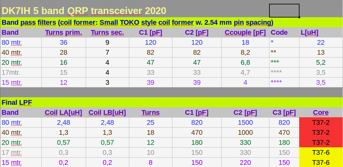
Hint: Inductance for the BPF coils have been measured with (probably) excess error ratio. Thus calculations are resulting in a different resonant frequency for the LCs when using Thompson’s formula!
Currently some additional tests with the the transmitter are pending, but full description will follow the next days. So, stay tuned! 😉
73 de Peter (DK7IH)
Hi Peter
Interesting to me that you choose T37-2 toroids for a 14MHz LPF. I have tended to use them at 3.5, maybe 7MHz, but not higher. I use this reference. http://toroids.info/T37-2.php
I’m pretty sure they will work but their characteristics may change at 14MHz or above.
Looking forward to reading more. Paul VK3HN.
Hi Paul, thanks for the hint. Data on toroid materials seems to be a little bit inconsistent. Another AMIDON website states a different usable frequency range for material #2:
“Frequency Range 2 Mhz – 30 Mhz”
http://www.amidoncorp.com/2-material-iron-powder-toroids/
I have to concede: I just donno! 😉
vy 73 de Peter
If you can fit the required inductance (few turns) and still get the required coupling with the red cores, they will work OK. The Q might not be ideal, but if it resonates with the desired bandwidth, then OK. For LPF’s in the transmitter the red cores might have higher loses. Also the receiver intercept point with the red cores at higher frequency might be inferior to the yellow cores. In fact PA3AKE went the other way with his famous band pass filters, he used YELLOW cores where RED was recommended, and BLACK cores where the YELLOW was with the goal of getting the best possible intercept point. He also used rather LARGE cores, T96’s instead of T50’s for the same reason.
Gee, why don’t you add some more relays and make it a 7 band rig so you can have the 17, 12, and 10 meter bands. 12 and 10 are opening up too these days, and that will only become more common as time goes on. Since you’re only interested in SSB I understand omitting 30, but what about 60? (Does DK land have that band?). Actually if you design those filters to have a bit more bandwidth, they could cover more than one band each on the higher end. I recall the filters in the Pic-A-Star were 1/2 octave wide to do that trick.
Hi there!
“Gee, why don’t you add some more relays and make it a 7 band rig so you can have the 17, 12, and 10 meter bands.”
Limited space always is an issue. 😉 But I’m planning to build a 10 or so band transceiver for ALL the RF ham bands. Let’s see! 😉 vy 73 de Peter (DK7IH)
To achieve wide HF coverage have you thought about doing an upconversion across HF, then down to a familiar fixed IF, a bit like uBitx? Or Farhan’s Minima? I’ve not tried dual conversion but it would make an interesting break from the single conversion superhet pattern. — VK3HN.
Hi Paul, yes I have conceived this design sometimes but I have never really got to try it. Maybe later. ;-)) vy 73 de Peter
Hi Paul, thanks a lot for the compliments. I’ll try my very best! 😉 73 de Peter
Good for working #EME
A single sideband contact between IZ1BPN in Italy and PI9CAM at the Dwingeloo Radio Observatory. IZ1BPN’s transmission is shifted up in pitch slightly to compensate for PI9CAM’s transmission being shifted down by the Doppler effect. (wsr88D nexrad) YourPeer, D.K.Alston alais:TarantulaPelts aka TD’84 🦚
Great web page! Keep up the good work.
🙂
hey Peter,
I believe that 39/9 turns on Toko-style 5mm formers is for 40m and not 80m, as I couldnt get those 22uH (max. 17.4uH with 39 turns, so it looks it needs even more). I noted on Micro42 that the 7MHz BPF has those 39/9 turns with 82p caps. I imagine I need to have the desired uH for specific band without those caps added, right?
It’s amazing, as on the universal PCB 3x7cm from China, you could built at least 5 band BPF set with their respective SMA sockets (using SMD caps 0805 fits great between the wholes on the PCB). Once I understand the relays, I wish I could have that implemented as per your suggestion in HF-6-Band-SSB-transceiver, where ULN2003 was used).
anyway, all the best!
Waldi