Abstract
The transmitter for this transceiver is designed to deliver a peak envelope power (PEP) of 10 watts on all bands from 80 to 15 meters. Due to its purpose (SSB amplification) it is a linear amplifier.
The circuit is equipped with 5 stages where the first one is a gain control stage containing a dual gate MOSFET whose gate 2 is controlled by a gain voltage from a digital-to-analog-converter (DAC), an MCP4725, and preset by values manually stored in the microntroller (MCU). This allows the user to compensate the decreasing gain when higher frequencies are used. The remaining stages are equipped with bipolar transistors.
The audio input stage of this transmitter uses a off-the-shelf designed integrated circuit (SSM2166 by Analog Devices) which is a microphone compressor for computer applications.
The DSB-generator succeeding the compressor is an integrated mixer of the AN612 type.
Afterwards the TX mixer section (NE612 active Gilbert Cell mixer) follows. After being processed by the band pass filter (BPF) the five stages of the transmitter push the filtered signal to the designed final power level:
- Gain control stage (40673 dual gate MOSFET)
- 1st amplifier (2N2222)
- Predriver (2SC2314)
- Driver stage (2x2SC2078)
- Final power amplifier (2x 2SC1969)
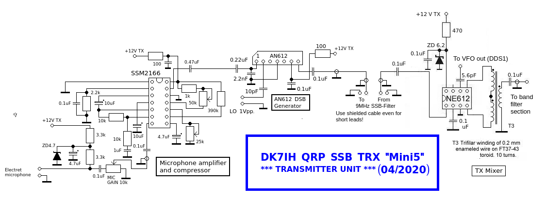
Audio stage and double sideband generator (DSB) and TX Mixer
This unit is designed for usage with an electrete microphone. Supply voltage is generated in a chain of 2 series switched 3.3k resistors, a 4.7V zener diode and a blocking capacitor. Following is an integrated circuite (IC), the SSM2166, which is a microphone amplifier and compressor circuit.
An AN612 integrated mixer forms the DSB generator in this circuit. There is no potentiometer for carrier suppression, in general carrier suppression of >45dB can be achieved with this simple circuit.
The resulting DSB signal is fed into the SSB filter that is placed in the receiver section. Usage of shielded cable with high shielding capacity is mandatory here for interconnecting the filter to the transmitter circuit. Even if stray coupling in high level radio frequency energy is not a severe issue on the interfrequency branch of the transmitter.
TX mixer is an NE612 with balanced output. This measure which will result in some extra dB concerning output gain.
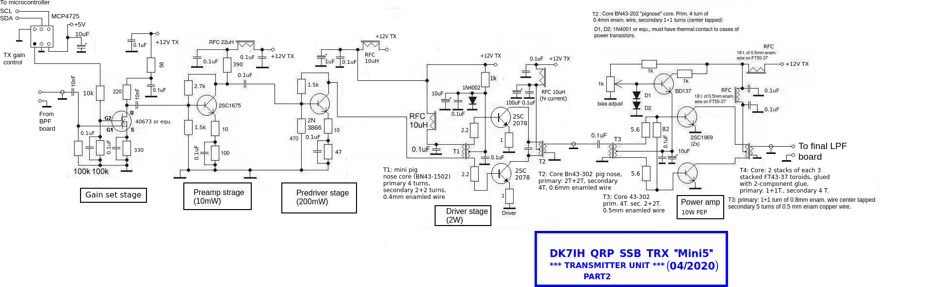
Power amplifier strip
A lot of introductory research had been done on a multi band QRP power transmitter with 10 watts of pep power when building the experimental 6 band transceiver. The general issue for a broadband power amplifier is the gain difference that occurs when band switching is applied. 3dB gain loss per octave is the rule of the thumb that is stated in lieterature and has proven to be correct under practical examinations..
An easy and reliable way to compensate this common gain loss, can be achieved using a programmable gain set stage at the entrance of the transmitter chain. This onset here is achieved by using a dual gate MOSFET transistor whose gate 2 is controlled directly via an I2C programmable digital-analog-converter (DAC). This DAC (MCP4725) is 12 bit wide, thus software in the MCU allows the user to set the gain in 4096 steps via the controls and store this value in the MUC’s EEPROM. After each band switch the respective value is recalled and subsequently sets the stage’s gain.
The amplifier strip presented here includes 2 push-pull stages as driver and final power amplifier. In contrast to the 6-band transmitter there is no “in-between” low-pass-filter.
All coil data is stated in the schematic. Pig nose cores are used in the final amp stages.
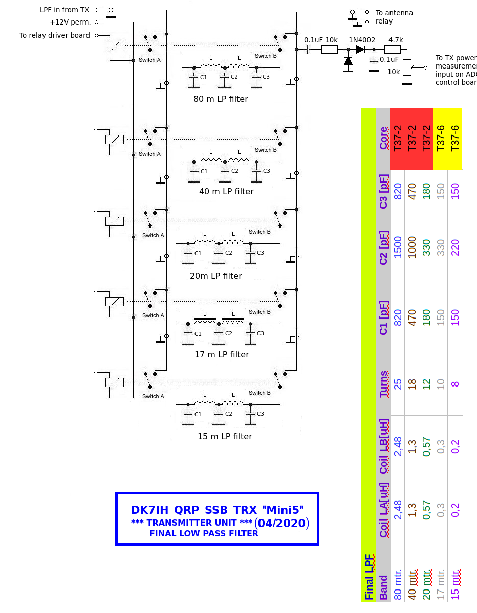
After the power amplifier the circuit terminates with the final low pass filter section. Simple 5 element filters are used.
When setting up the circuit on a PCB or veroboard keep in mind that the 15m filter section should be placed in the closest position to the input/output connector to save lead length! Or to say in other words: Reverse the filter order in the schematic!
Vy 73 de Peter (DK7IH) and thanks for watching!
Your transmitter design is a fine balance if performance and simplicity. The SSM2166 is an ideal audio stage and the AN612 a novel balanced mod. I am building an SSB rig just now using 1496es and parts count is high! Also your idea to use a digipot on I2C to maintain gain above 10MHz is smart. Keep up your innovative design work. 73Paul VK3HN.