Follow-up articles published so far:
- Digital and analog main units: VFO, Local oscillator, Display, TX-Gain control
- Receiver unit
- Transmitter unit
Abstract
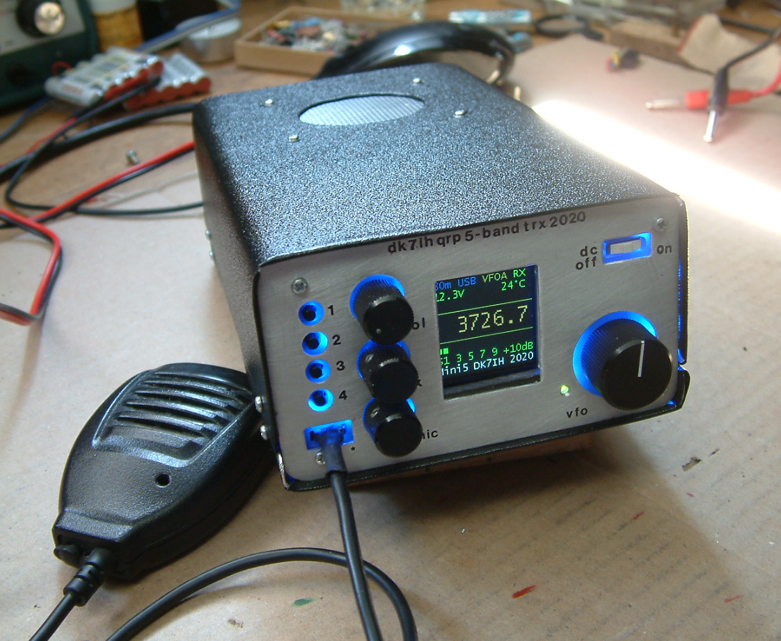
A compact SSB transmitter/receiver will be presented. This unit covers 5 bands within the amateur radio spectrum (3.5, 7, 14, 21 and 28 MHz). After modification the 28Mhz band has been removed and been replaced by 18MHz. The receiver is a single conversion unit with an interfrequency of 9 MHz. The transmitter uses 5 stages and has got a power level of 10 watts PEP output.
Frequency generation is done by integrated ready made modules, in this project a Si5351 as VFO and LO. Microcontroller (MCU) is an Arduino Pro mini AtMega328 driving a colored TFT LCD with ST7735 chipset.
The whole device has been constructed in SMD as far as possible (that if respective components are available in SMD) but can also be setup by using “thru hole” techniques or mixed installations.
The unit is built into into a mounting frame of aluminum sheets of standardized width. Size of the whole radio is 17 x 12 x 5 centimeters. It is, to a certain degree, the “Little Brother” of the “Midi6“-Transceiver that had been designed mainly for experimental purposes.
Description
Building a multiband QRP transceiver project is a challenging project for the radio amateur. The even more challenging matter is to build it as neat as possible. The “Midi6” transceiver has been an interesting step which made me learn a lot of things. But it is a much too bulky for my needs (I prefer compact and lightweight portable gear for traveling, hiking etc. ) On the other hand I found that I don’t really need 160m installed in the radio (due to antenna limitations here at my site) which defined the next multibander having a “classical” (i. e. 70s) layout with 80, 40, 20, 18 and 10 meters.
An important point was to use ready made modules or breakout boards for the major digital and analog circuits:
- Microcontroller: Arduino Pro Mini ATMega328
- VFO: AD9850 board from China
- LO: Si5351 breakoutboard by Adafruit
Design considerations
First I thought about using the Si5351 as VFO and LO because it contains 3 oscillators on one chip. But I gave that idea away very fast because there were to many spurious signals and the thus the receiver had to many “birdies” which I don’t accept. Having had some of the Chinese made AD9850 boards still here on the shelf I gave that type of oscillator one a try and was finally relatively happy with receiver performance.
The microntroller and its application also has been a challenge because for a multiband transceiver an Arduino Pro Mini might be a little bit weak because the number of ports is very limited. But it finally worked out when planning is carefully done and optimizing is brought to its limits. The port usage is as follows:
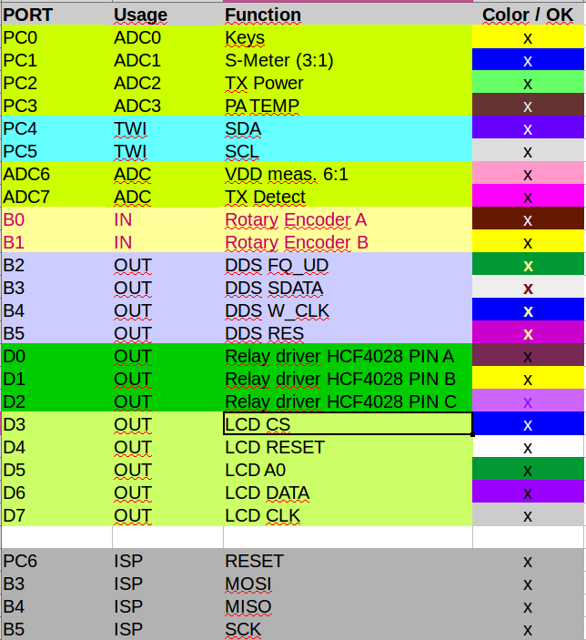
ISP leads are used for controlling the DDS and for uploading the software to the controller. This is done because the inputs of the DDS are high Z inputs that do not affect the ISP data transfer. On the other hand the programmer goes to high Z if there is no data to be sent to the controller. Thus testing the radio is possible when programming leads are connected.
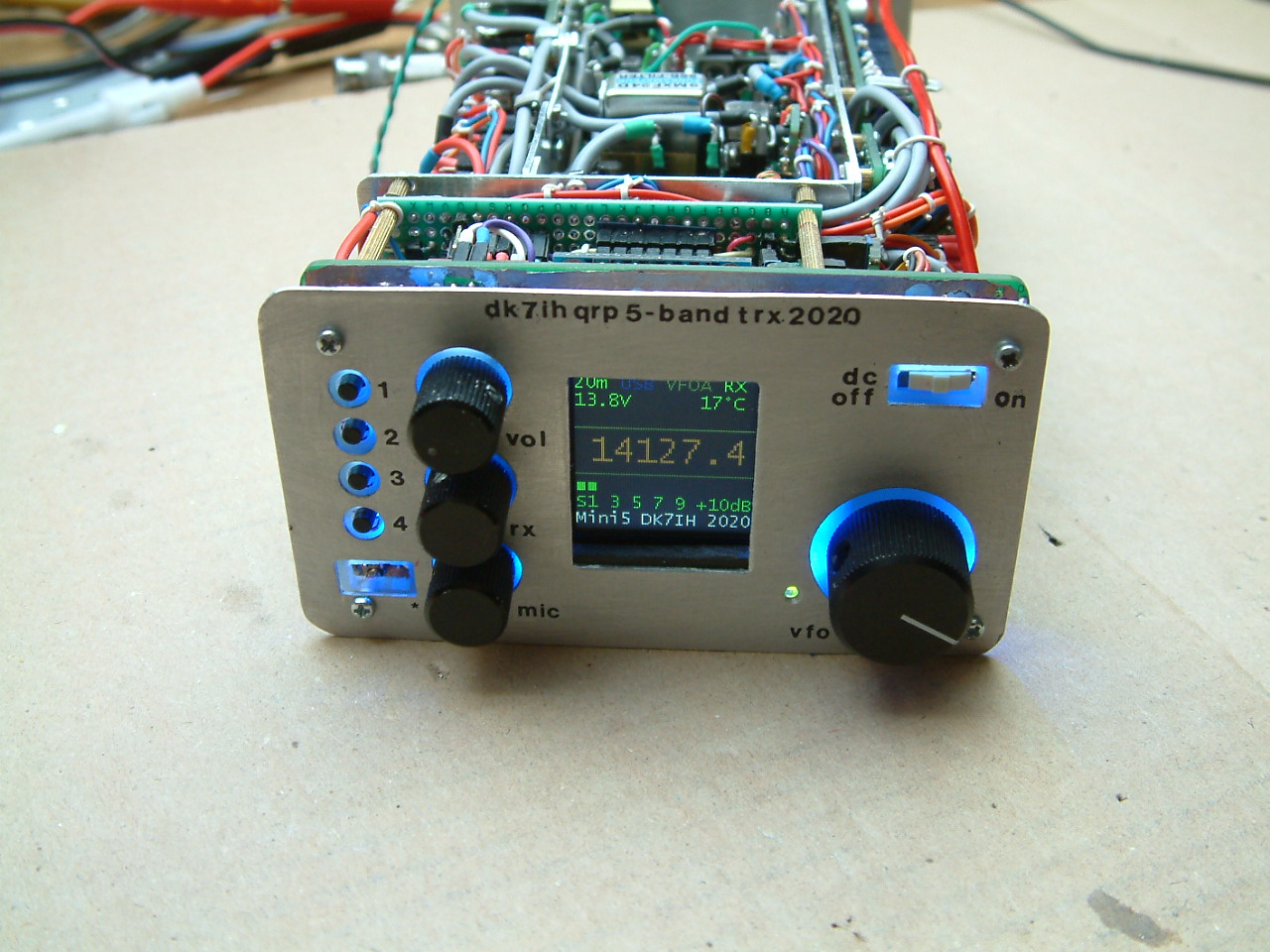
The LCD is an ST7735 TFT colored display because I found the OLEDs with 1306 and 1106 drivers to noisy on the higher bands where band noise is weak and therefore digital noise produced in the radio comes more into the foreground. And, above all, a colored display makes much more impression than an ordinary monochrome one. 😉
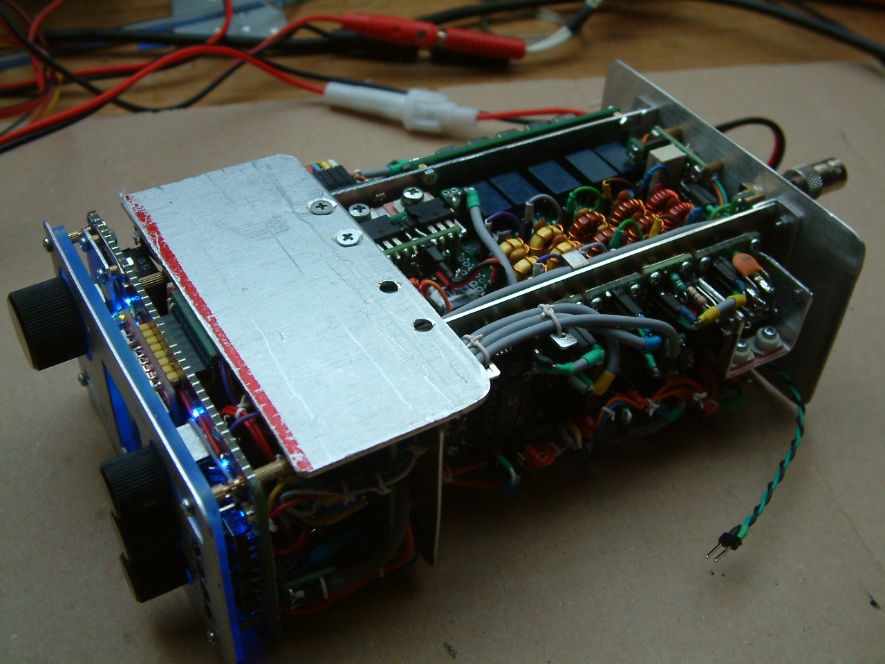
Mechanical construction and transceiver units
For this radio I ordered aluminum strips holding a width of 5 centimeters via ebay. Thickness is 1.5 mm. From this material a very rugged frame has been constructed that gives the whole rig a very good mechanical stability.
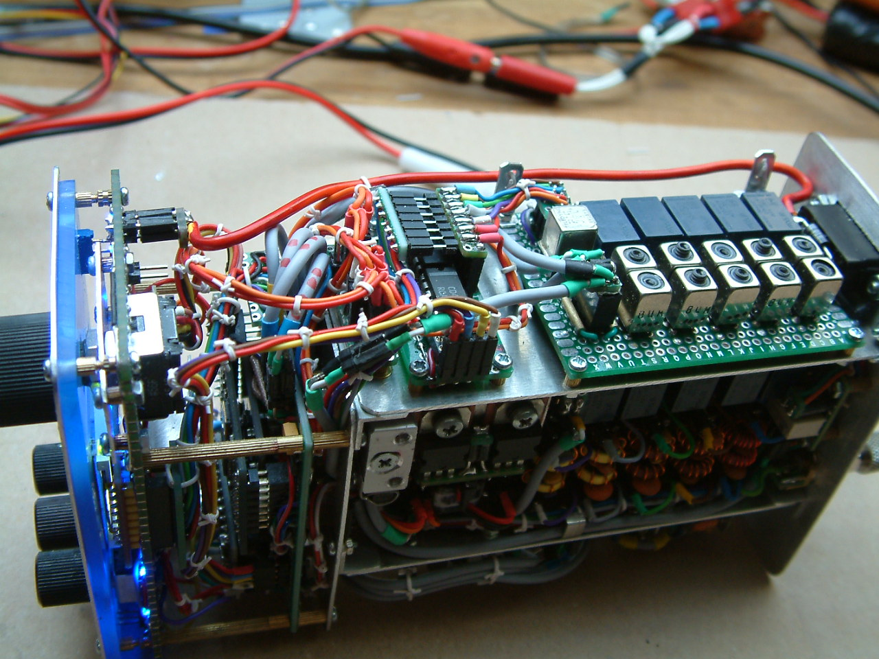
Major units in this construction
The rig is very much on the basis of single modules. Each unit section is soldered to a very small piece of veroboard that has been cut out from a larger piece of material. It is fixed to the aluminum basis by using inserted nuts with M2 screw thread. The main advantage is: If one unit fails it is easy to reconstruct it and put it to the place the predecessor has been mounted and second grounding is excellent because the small single units don’t require long grounding leads because the boards are very small in size and the 4 corners all have ground potential. Particularly for the transmitter I can say that I had never any unwanted oscillations.
The transmitter is 100% stable on all the 5 bands, which was not the way with the first “Gimme 5”-Transceiver that had severe layout problems in the transmitter having the initial BPFs very close to the final rf power stage. But in the end you should be knowing more than with the beginning pf a project. So true here. 😉
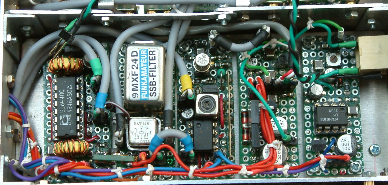
The picture shows a close-up of the receiver section that consists of 5 single units (from the left)
- Dual-gate MOSFET preamplifier (in the picture veiled by shielded cables) and rx mixer (SL6440),
- SSB Filter 9 MHz by box73.de,
- Interfrequency amplifier (MC1350) and product detector (dual gate MOSFET),
- audio preamp (BC547) and main amp (3 transistors, the 2 finals in push-pull circuit),
- AGC with OP (LM358) and bipolar transistors as voltage regulators.
The same technique has been used for the transmitter:
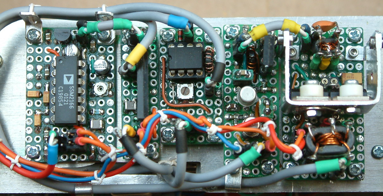
Starting from the left you notice an SSM2166 microphone compressor ic by Analog Device which also is the main microphone amplifier. Next is an AN612 mixer as DSB generator, followed by an NE612 serving as transmit mixer.
The second board from the right is a 3 stage unit to bring the transmit signal to a power level of about 150mW (Dual gate MOSFET, 2N2222 and 2SC2314 as active semiconductors in this order). On the right a push-pull stage equipped with 2 2SC2078 and relatively high emitter degeneration (2 Ohms for each transistor) brings the power up to 500mW.
Transmitter gain can be controlled with an MCP4725 digital-to-analog converter (DAC) that is set for each band individually and helps much to compensate gain increase on the lower bands. This DAC is also connected to the microcontroller’s I²C-bus and data for each band is saved in EEPROM and is being recalled if a certain band is switched.
The main amp is centered on the center side of the mainframe:
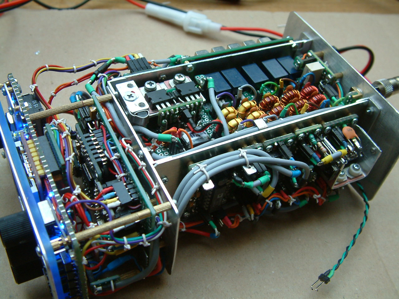
On the left side of the tx pa unit there are 2 power transistors (2SC1969 by eleflow) mounted to a small strip of 3mm thick aluminum that is connected to another much thicker block of Al. Here a large heatsink can be mounted when the device is under test or finally fixed into the cabinet when using the aluminum cabinet as heatsink. Connected to the aluminum block there is the temperature sensor (KTY 81-110) that allows permanent check of the transistors’ temperature and that will lead to a warning on the LCD when excess temperature is detected.
The output transformer can be found under the two PA transistors and therefore is not visible here. This “stacked” construction saves very much space. PA transistors are connecting to 2.54 mm socket strips which makes the pair of semiconductors removable and allows access to the power transformer underneath.
On the right of the PA section there are the low pass filters for each band switched by a single relay.
Band filters are shared for transmitter and receiver and are switched to the respective branch by using relays. Left of the BPF unit there is a logical unit (HCF4028 BCD encoder and an ULN 2003 relay driver integrated circuit). This allows switching 5 relays by just using 3 binary coded controller output ports.
Software is written in C for AVR controllers using the GNU C compiler under Linux. The code will be discussed in the respective article that is going to follow this introduction.
I strongly recommend to stay tuned for the next articles covering this transceiver and giving details for each unit! 😉
73 de Peter (DK7IH)
You could have probably shared the SPI interface with the LCD and the DDS (I hate doing SPI via bitbanging in software). IIRC, the serial USART can also be used in SPI mode, so you actually have two H/W SPI interfaces on the atmega (It looks like you’re not using the serial port for a bootloader or for computer control). Many hams are using the SI5351 as a vfo without having problems with spurs. I suppose it depends on how the clocks are assigned. Two of them share a common PLL, the clock with its own PLL should probably be used as the VFO. I’ve used the AD9851 in the past. I got the DDS60 kit) and it does make for a good VFO, though the AD995x series with a higher frequency clock and 14bit D/A is cleaner.
I’m quite amazed at your projects, but I wonder how you design them. Do you bread board the circuits first and test, and then rebuild into the final enclosure, or do you build modules to the guessed at final size and then build an enclosure around them?
I usually have a box size picked out before I start a project, and hope it’s big enough!
Hi WA2MZE,
indeed, sharing the SPI lines was my first idea also. But then I quickly found out, that the “Chip Select”-Pin is not accessible with my China-made AD9850 board. And I have found out that using the “FQ_UD”-line with the DDS as an “enable/disable” line does not mean that you will block the input to a 100% . I found that random frequency changes occurred if not using the CS-line correctly.
Concerning the Si5351: Well, I think some research is mandatory concerning software optimization for me. Maybe there are clues I have not found so far. 😉
The reason why I did not use an AD995x this time was that I wanted to apply the available circuits from the Chinese market that I still have here. And I found that the Si5351 just fits under the AD9850 board which made me save a lot of space. 😉
The most circuits I had tested using a breadboard before they were soldered to the veroboard. But “the proof of the pudding is the eating” as people say, so I solder them to a veroboard an then compare final findings. Particularly in cases they have to work together with other boards. Breadboard testing only provides limited results because concerning rf circuits using a breadboard often is misleading due to stray inductance and/or capacities. Thus, as soon as the the complexity of a circuit exceeds a certain level, the breadboard test will fail.
Vy 73 de Peter (DK7IH) and HAPPY EASTER!
Hallo Peter (DK7IH),
Ich möchte Sie nur wissen lassen, dass Ihr Projekt wunderbar ist !!!
Vy 73 de Oliver 9H1SS.
Vielen Dank! 🙂 73 de Peter (DK7IH)
hola Peter!,mi nombre es Walter (LU1ABV) y me interesa muchisimo el equipo qrp ssb de 6 bandas ,esos equipos los construis y los comercializas vos? o de que manera puedo obtener uno?,aca en Argentina en estos momentos esta muy dificil importar equipos y componentes,pero ese equipo me guso muchisimo y queria saber de que maanera puedo llegar a tener uno,o si puedo obtener los pcb para su construccion y todos los datos,desde ya muchisimas gracias y 73″s dx de walter LU1ABV.
Hola Walter, lamentablemente no hay ofertas comerciales para los dispositivos que estoy describiendo aquí. Hay experimentos, piezas individuales y configuraciones de prueba. Desafortunadamente, tampoco tengo ningún diseño de placa de circuito. ¡Lo siento mucho! Vy 73 de Peter
This is a nice build. I am excited to see the progress and build one for myself.
I don’t understand the SMD comment as no SMD devices are shown? Kudos for design, but SMD it is not!
Well, then I say it more precisely: All the resistors and capacitors, so the vast majority of components, are in SMD. 😉
Hallo Peter.
Tolles Projekt. Würde sowas direkt kaufen wenn es produziert würde.
73‘s LX1KU
Hi, vielen Dank! Leider kann ich entsprechende Ware anbieten, da mir dazu die Ressourcen fehlen. Sri! 73 de Peter
Great job and thank you for all the information and hard work you have done.
I want one! 😎
Me too!
Hi Peter. I like to look of your design but I would only make it for 20m.
Do you have or would you share your circuit diagram with me please.
Thanks.
Hi Paul,
you will find the schematics in the follow-up articles to this introductory post:
Oscillators:
https://dk7ih.de/2020/04/gimme-five-reloaded-a-compact-5-band-qrp-ssb-transceiver-in-smd-technology-vfo-lo-mcu-etc/
Receiver:
https://dk7ih.de/2020/04/gimme-five-reloaded-a-compact-5-band-qrp-ssb-transceiver-in-smd-technology-the-receiver/
New band layout (Now: 80, 40, 20, 17 and 15m):
https://dk7ih.de/2020/04/gimme-five-reloaded-a-compact-5-band-qrp-ssb-transceiver-in-smd-technology-new-band-layout/
Transmitter:
https://dk7ih.de/2020/04/gimme-five-reloaded-a-compact-5-band-qrp-ssb-transceiver-in-smd-technology-the-transmitter/
https://dk7ih.de/2020/04/gimme-five-reloaded-a-compact-5-band-qrp-ssb-transceiver-in-smd-technology-practical-transmitter-setup/
https://dk7ih.de/2020/04/gimme-five-reloaded-a-compact-5-band-qrp-ssb-transceiver-in-smd-technology-transmitter-spectrum-analysis/
Hope that helps!
vy 73 de Peter
Hi Peter,
Where did you find the 2mm screws and spacers ?
Thanks and all the best for 2022.
73’s Olivier
Bonjour Olivier!
These screws and spacers are available from Chinese vendors via ebay:
https://www.ebay.de/itm/133838433902?hash=item1f29646e6e:g:9HEAAOSwXsNhCnVT
This is ebay.de but I think it should also work with ebay.fr
I usually use search strings like “screws m2” or so….
vy 73 de Peter