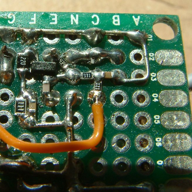
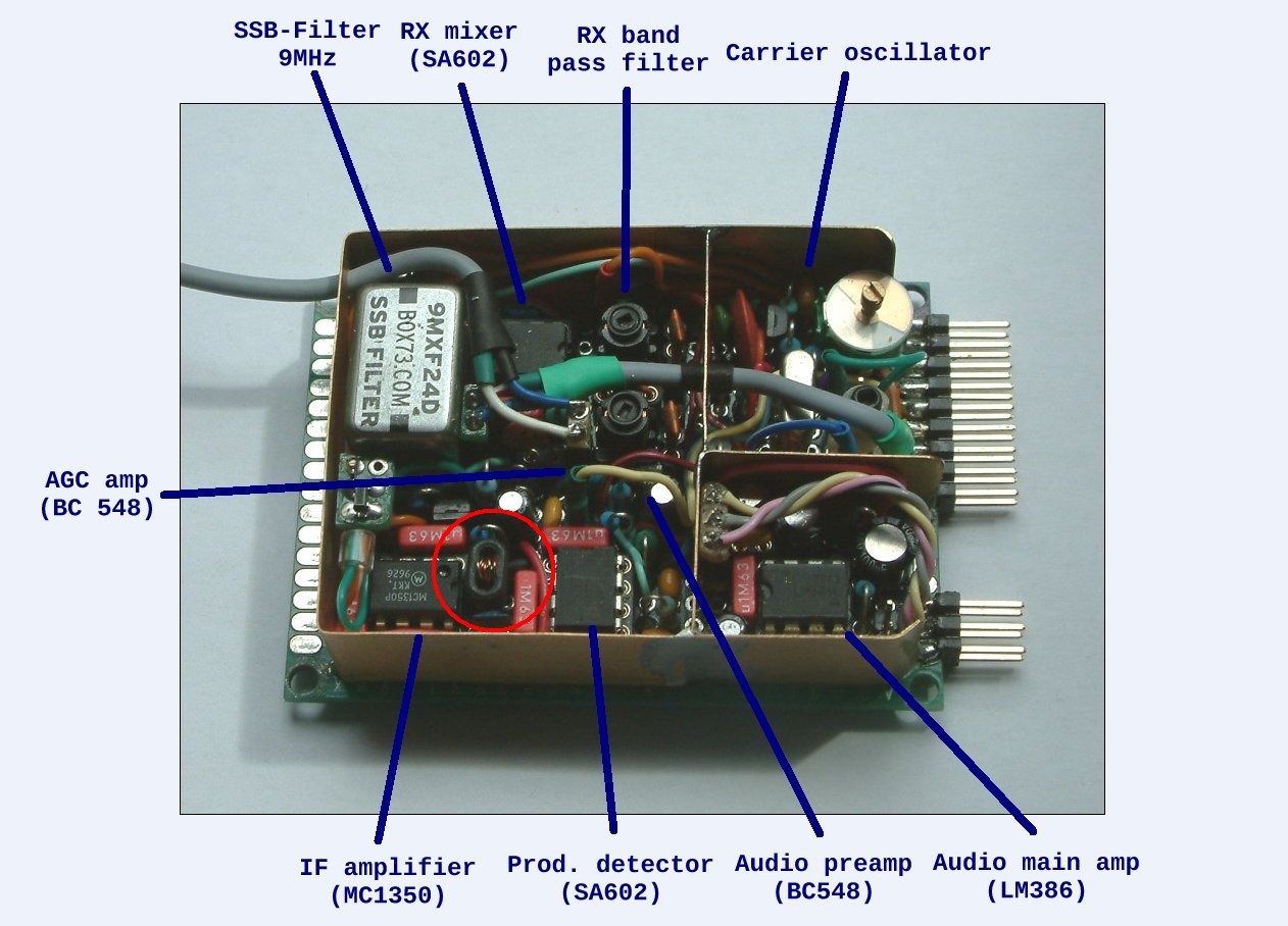
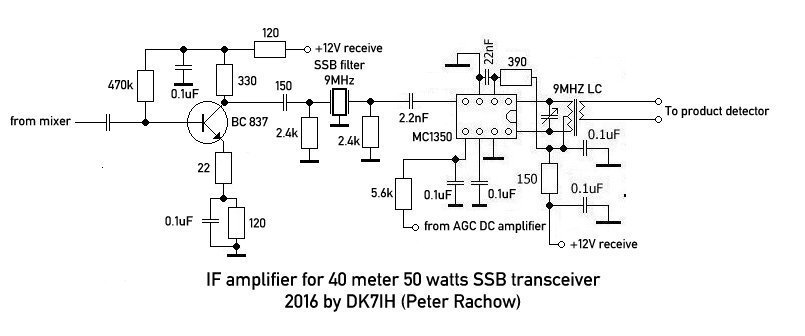
The if amplifier has been slightly revised. I added a preamplifier after the 1st mixer to enhance overall gain. Due to the fact that the veroboard is crowded with the components that had already been installed, the preamplifier has been worked out in SMD technology using the reminaing space on the reverse side of the board underneath the SSB filter were still some room has been available:

This new part of the circuit is not marked in the block diagram I’ve pageed some days ago. As main amplifier of this stage, MC 1350 is used. Due to space saving reasons the tuned circuit to terminate the if amplifier IC has been made of a very smmall pig-nose core:

The parallel capacitor has been experimentally optimized by putting various capacitors into a 2 pin part of a socket strip and keeping the best valued. The MC1350 is gained controlled by an AGC amplifier and DC rectifier section to be described later. Please notice the correct termination of the SSB filter with 2 resistors 2.4 kOhms each.

Thanks for watching! Vy 73 de Peter (DK7IH)
Hi, Peter! I did noticed the 2,4k resistors, but cant see any good of a left one. Filter on a left side is terminated to the impedance around 300-j120 Ohm (amplifier output with a capacitor in series). On a right its terminated to 2,4k with MC1350 input (say 3,5k) in parallel = around 1,7k.
What was a circuit between mixer and filter before You decided to add an amplifier?
Yes, basiclally you’re right. All in all its impossible to get the 100% proper termination of the filter. When you calculate the input impedance of the MC1350 you also have to calculate the capacitive reactance of the 2.2nF capacitor in seies. THe same is true for the input side. The 2.4k resistors are just to provide something like an estimated termination better than nothing.
73 de Peter
Dear Peter, now i build your 5 band transceiver. First i drow pcb layout by using sprint layout 6.0 programm. After that, i pressed pcb’s by using posiyive20 & montaged components. A few days ago i tryed the device, it worked perfectly, both transmitter & receiver for 7mhz & 14mhz bands. Buy there is a problem: unfortunately, my AGC circuit does not work. i tested all probabilities for AGC device, but not find any negative result. What can i do? My be IC is out of order.
However, your project is excellent.
I continue follow your projects.
73.
TA3IHD
Hi TA3IHD,
first my congrats for bringing the 5-band-TRX to live! Nice to read that other hams can profit from my work.
Some hints on the problems you described:
For the RX preamp (with the dual gate MOSFET) the BF961 should work as well. Maybe biasing this Q is different from the 40673. Please check the data sheet for more info. With the 40673 the G2 voltage should be around +6V DC for max. gain.
Concerning the AGC. I will check the schematic later, maybe there is a problem with this one. The OP sometimes fails (had two “dead” ones in my box). But wait until I dropped you another message when I’ve checked the scheme.
73 so far from Peter (DK7IH)