The receiver had to match a lot of requirements that should be described first:
- Particularly on the lower bands and with effective long wire antennas the receiver front end will see high signal levels that it has to cope with. IMD always is a serious topic in this case.
- Sensitivity particularly on the higher bands, where noise level is ow and signals are weak, is also an issue.
- Dynamic range and extensive AGC gain compensation should be as high as possible.
This lead to a circuit that has proven its stability in lots of my radios:
- Band filtering for each band with a double and loosely coupled LC circuits
- Dual-Gate MOSFET (part of the AGC chain) as the first amplifier
- Diode ring mixer (with Schottky diodes)
- Post mixer amplifier with Dual-Gate MOSFET (part of the AGC chain)
- SSB Filter (now 10.7 MHz) also used for transmitter (relay switched)
- Main IF amplifier with MC1350 (part of the AGC chain)
- Audio preamp with bipolar transistor
- Audio final amp: (once again! 😉 ) LM386
Before describing the receiver itself we will have look at the band pass filter unit, that is shared between receiver and transmitter:
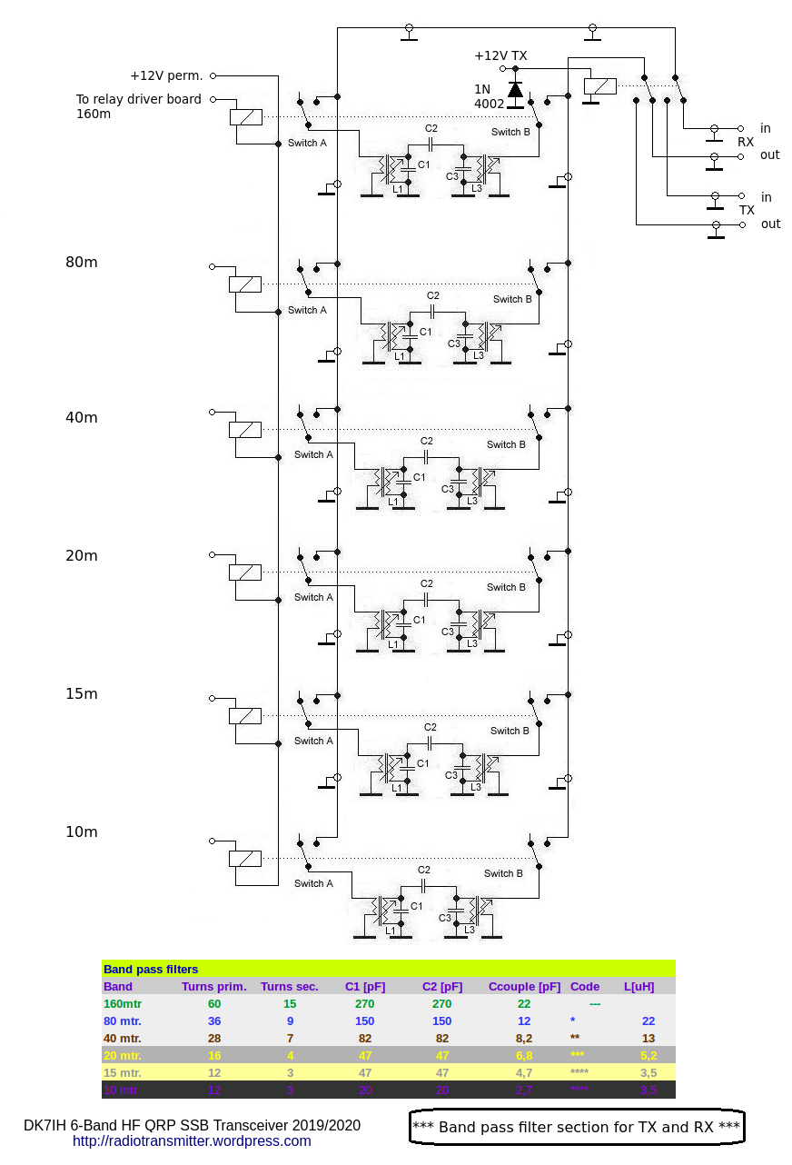
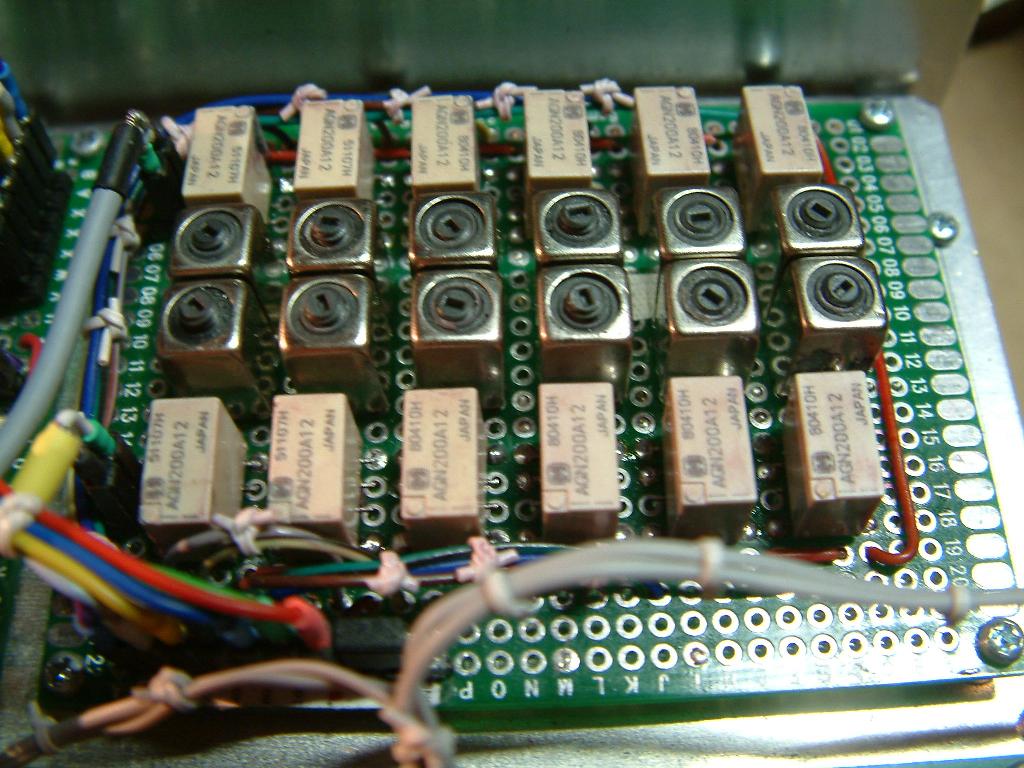
To minimize stray energy traveling from the input to the output of the filter, two SMD relays have been used on each side of the filter per band. And to reduce feedback fromt the transmitter (when the BPF is used to filter the TX signal after the TX mixer) the filter has been placed far away from the TX amplifier section.With an overwhelming result: The transmitter is nearly unconditionally stable now (compared to the TX section used in the “Give me 5”-Transceiver that had severe shortcoming in this aspect.
Control leads for the relays follow a designated coding scheme:
- 160m: green
- 80m: blue
- 40m: brown
- 20m: yellow
- 15m: grey
- 10m: violet
The receiver’s circuit
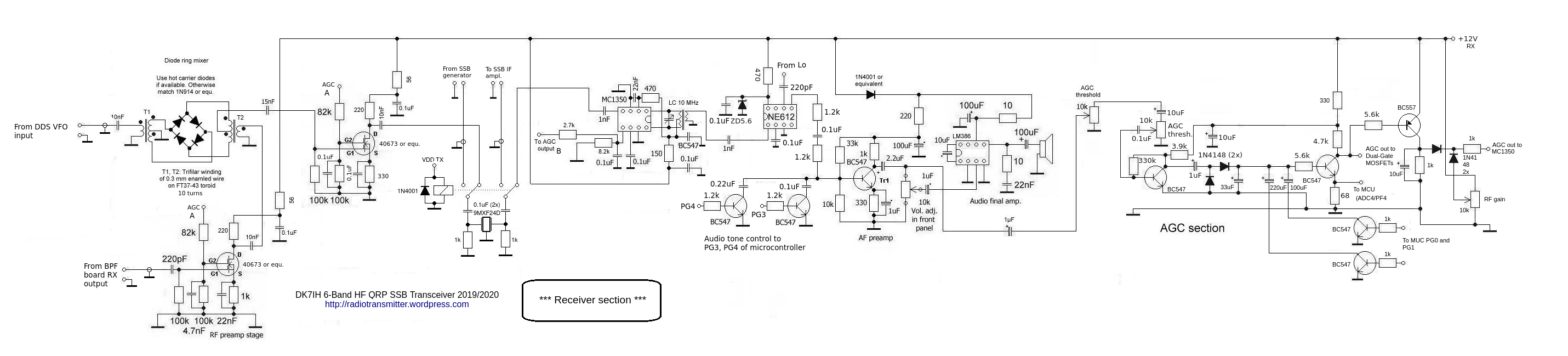
VFO signal is coupled into the DBM via a 10nF capacitor. The same is valid for the amplified RF signal from the output of the first amplifier stage using a Dual-Gate MOSFET (40676, BF900 or equ.).
Another Dual-Gate MOSFET is used as the page-mixer amplifier. All Dual-Gate MOSFETs so far are part of the AGC-Chain. This maximizes the possible gain swing to about 40 to 50 db. and enhances the receiver’s capability to handle even the strongest signal levels without distorting the output signal and the end of the audio chain.
Next is the SSB-Filter. Due to this is an “experimental” transceiver, the filter has not been soldered to the circuit board. Instead it is fixed with an aluminum clamp into two parts of header strips. Thus I can compare numerous SSB-Filters (9-, 10.695-, 10.7-MHz off-the-shelf ones, various home made ladder filters etc.). Here the different performance is very interesting to be explored.
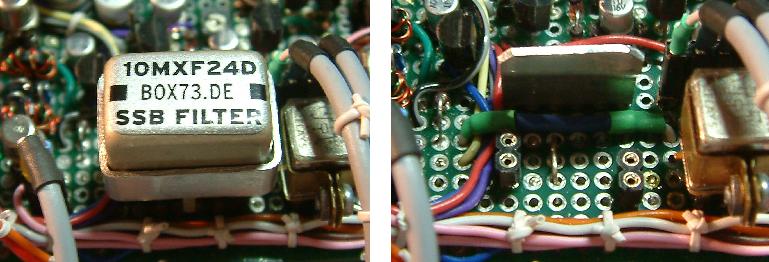
The filter is accompanied by a special rf relay (manufacturer “Teledyne” with excellent performance concerning separation for the two channels) so that it can be used as the SSB filter for the transmitter section.
After the filter section the IF amplifier follows. This one uses an MC1350 video amp (old but good and still available, even in SMD!) and this IC also is controlled by AGC. The input is unbalanced (PIN6 to GND) the output is balanced and terminated with a tuned circuit.
Demodulator is an SA602 mixer IC.
After that the signal is handed over to the audio chain. But before the signal is processed in the next stage the frequency range is limited by a low-pass filter to reduce hiss. This filter also has two switched capacitors (controlled by MCU via NPN-driver stages) to adapt the sound to the preferred settings of the user. The software contains a respective function.
The audio amplifier consists of two sections: A preamp with a bipolar transistor and the inevitable and well-know LM386.
The full circuit on a 6×8 cm veroboard:
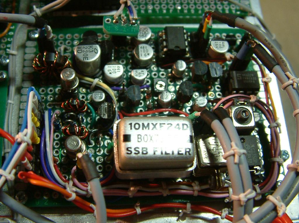
Starting from left top corner there is a 1:4 input transformer (not in the schematic), the preamp, the DBM, page mixer amp, SSB filter, relay, MC1350 as IF amp, demodulator and 2 stages of audio amp.
Receiver performance
Performance is excellent. The circuit has no problem with high signal levels (in-band and out-of-band) especially on 40 meters. No IMD problems are noticeable even when used with high gain antennas like a 2×25 meter doublet with a tuner. On the higher bands noise figure is pretty OK what I think is based on the usage of Dual-Gate MOSFETs in 2 of the 3 amplifier stages. The MC1350 deteriorates this to a certain degree but is still very much acceptable for a shortwave radio.
Vy 73 de Peter
10.7 Mhz is a poor choice of IF on the 15 meter band if you are using low side injection! The IF looks like it could be a natural for a 40/20 meter band image rig, until you realize that harmonics of the LO will cause birdies on 40 meters. With the AD9950 DDS, and using high side injection it will work, but there still are issues of the IF second harmonic leaking into the 15 meter band, a possible birdie source. The only reason this IF is popular, is because of all the IF filters made for this frequency that were used on the US Citizens band, the frequency was chosen to make use of available FM radio IF transformers. Would have been better to add an external padding capacitor, and tune those IF cans down to 9 Mhz!
Hi WA2MZE! In fact there is a very little birdie on 21.4 MHz. But it does not disturb very much. Currently experiments are on the agenda with various filters and these are more important than a little interference on a band I can not use in these days. Later I will finally decide which filter to use.
BTW: A similar problem occurs also with a 10.7 MHz filter and the 20 meter band when the VFO is operating below reception frequency.
The crucial frequency here is fRx= 14267kHz +/- some kHz. For this frequency the VFO generates an oscillator frequency of 3567kHz +/- some kc, which has the 4th harmonic at 14268kHz. So there is a point where you are going to receive the 4th harmonic of the oscillator.
Vy 73 de Peter
By the way: When you download the latest source file you can see the various IF options I have implemented as #defines. Vy 73 de Peter
https://github.com/DK7IH/6_Band_QRP_HF_Trannsceiver/blob/master/midi6.c
congrats for this project,very very nice !Peter,tell me pls which PNP transistors using in AGC circuits ?73 de 9a3xz.Mikele.
Hi Mikele, in the AGC you can use all PNP AF types like BC557 etc. Vy 73 de Peter
thanks so much,i wanna said again..beautiful project a always.Where you get the coils in BPF ?
Hi Mikele,
the coils are available from pollin.de. Surf to
https://www.pollin.de/p/einstellbare-induktivitaet-3l-fe-349-250512
(German only but GOOGLE translator will help 😉 )
73 de Peter (DK7IH)
Any Idea where to get those 8uh adjustable coils from. They do not seem to allow the United States delivery.
Would this be a suitable replacement for the coils? https://www.coilcraft.com/en-us/products/rf/tunable-rf-inductors/vertical-mount/slot7/7m3-682/
Yes. it would. But the pricing is extremely high. I purchase them from a German surplus supplier:
https://www.pollin.de/p/einstellbare-induktivitaet-3l-fe-349-250512
As 1USD is nearly equivalent to 1€ currently they sell for 30 Cents.
Vy 73 de Peter
thanks Peter for nice information.
Hallo Peter
Thank you for your efforts made to share your projects with us.
I’m a bit lost with “primary” versus “secondary” in regards to the band pass filters and the theory behind.
Let’s take the 80m filter: 36prim and 9sec
Are the 36 windings towards the antenna and the RF-preamp or towards the couple capacitor C2?
In regards to the theory: when I remember right the impedance of a parallel LC is equal to R in case of resonance. Are the number of windings connected to the antenna just a result of its L multiplied with 2*pi*f to reach a Z of 50 Ohm or is it a transformation of the Z of the parallel LC?
Thank you – und viele Grüsse aus Basel
Matthias
Hi Matthias, thanks for your question, here is a brief answer: “Primary in my terms is the entry side of the transformer, in transmitters usually the one where the collector of the previous stage is connected to. In power transmitter stages the output impedance commonly is much higher than input impedance of the sugsequent stage.
In receivers this is more or less handled the same way. In tuned circuits “primary” is the side where the tuning cap is sited.
The winding rate for the receiver coils (usually 1:4) is more or less fixed within my circuits. I accept a certain mismatch here, only keeping an eye on the fact that the input stages that carry “high” impedance (e. g. the gate1 of a dual gate mosfet) “sees” the high impedance side of the tuned circuit. Exact matching is more or less “luxury” and not that imprtant that it is in transmitter stages.
vy 73 de Peter
Thank you Peter for your explanations.
73 de Matthias
Peter, Where do you source components like the SSB Filter and tunable transformer’s, coils these days?
Thanks. Ed, N5EM
Hello Ed, the SSB-Filters are purchased from German vendor box73.de and the 8uH inductors come from pollin.de:
https://www.box73.de/index.php?cPath=82_100_163
https://www.pollin.de/p/einstellbare-induktivitaet-3l-fe-349-250512?
vy 73 de Peter, DK7IH
Thanks, very much. A beautiful piece of homebrew!
Hello Peter,
Congratulations on all the work and the achievements that you propose. I have a problem with the AGC of the MC1350 of my mounting of the receiver. It is always at 12v. The potentiometer of the Gain RF also has no effect.
The AGC of 40673 works well.
Without taking too much of your time you can advise me. Everything else: OK
Thank you again for your achievements.
Hi Jean-Pierre,
strange thing. When you desolder the 5.6k R leading to the base of the BC557 PNP transistor , are there any changes? 73 de Peter (DK7IH)
Hallo Peter,
kannst Du mir bitte einen Tipp geben, wie Du die Induktivitäten zerstörungsfrei zerlegt bekommen hast?
Bei mir sieht das im Moment so aus, dass nur jede fünfte das Zerlegen überlebt. Falls das hier zu umständlich zu erklären ist, würde ich Dich sonst gerne auch kurz anrufen.
Gruß,
Torsten – DL2SUF
Hallo Thorsten,
das Zerlegen ist in der Tat nicht so einfach. Ich versuche mal, meine Technik zu beschreiben.
Zuerst habe ich mir eine Art “Ausdrückwerkzeug” gebaut. Aus einem Holzstückchen steht ein Messingrohr mit einem Durchmesser von 5mm wenige Millimeter heraus.
https://radiotransmitter.files.wordpress.com/2020/05/ausdrueckvorrichtung.png
Dann setzt man die Spule mit dem oberen Ende (dort wo der Kern eingedreht wird), mit dem Ferritbecher zentral auf dieses Messingrohr.
Für den nächsten Schritt benötigt man eine Zange mit sehr dünnen Spitzen. Die Zange wird leicht geöffnet und die Spitzen so an den unteren Rand der Spule gehalten, dass diese beim Abgleiten des Bechers vom Spulenkörper diesen nicht berühren. Man vermeidet dadurch die Zerstörung der Spule.
Nun drückt man die Zange mit sehr viel Kraft nach unten, so dass der Becher von der Spule abgeschoben wird. Dabei hört man aber recht früh wieder auf, dreht die Spule um 180° und macht auf der Gegenseite weiter. Es sind jeweils nur 0,5 bis 1 mm die der Becher jeweils geschoben wird. Man muss langsam, vorsichtig und trotzdem mit viel Kraft arbeiten.
Dieses Spiel wird solange wiederholt, bis der Becher von der Spule entfernt ist.
So, ich hoffe, das war einigermaßen verständlich. Die entscheidenden Punkte sind die Ausdrückvorrichtung und die Spitzzange.
vy 73 de Peter
Hello Peter,
Can you tell me what the LC 10 MHz section is made of? It looks like a center tapped choke of some kind but I’m not sure. Also do you have a tally of all the components used?
Hello Dion,
I’m not quite sure if I get you right, you asked:
Actually in the band filters there is no 10MHz section because this is an SSB transceiver. If you mean the 10-Meter section,, this is 12turns primary, 3 turns secondary with C.parallel of 20 or 22pF and a 2.7pF coupler capacitor. Hope, I got you right…
And, no, the coils are not tapped, they are just a primary and a secondary with winding ration 4:1
If I didn’t get it right, please ask once more! 🙂
vy 73 de Peter
I new to a lot of this so just working out the symbols. In the Receiver section coming off the MC1350 there is a variable capacitor connected to a transformer at least I think that is a transformer? That is where I saw the LC 10 MHz. Also, sorry this may sound juvenile, but when you say +12V RX or +12V TX that is the power supplied by the TX/RX switch Board right and the +12V Perm is to source. I just got my amateur license and wanted to give this a try to help learn.
Hi Dion, OK, now I know. And you are right. I have used a 10MHz interfrequency when drawing the schematic but later I have changed it to 9MHz. Now it’s clear, thanks for the hint.
The coil following the MC1350 indeed is center tapped. For this interfrequency I usually use 16 turns (the same data like the coils for 20 meter btw). As the MC1350 has a symmetrical output both branches are used (pin 1 and pin 8). The DC is then fed into the tap of the coil to supply the amplifier stage.
For the reciever I sometimes use 2 power supplies: +12V RX and +12V permanent. This is because I want to avoid the “plop” sound when the radio switches from TX mode to RX mode. The “plop” is avoided to a large extent when the audio power amplifier is not cut from DC power when not in use during transmit periods. In this radio it has been an experiment with that technique.
BTW: Congrats for having the gained the ham license! 🙂
Vy 73 de Peter (DK7IH)
Thank you for the explanation I really appreciate it.