This unit has been designed to convert the signal of the SSB modulator to the desired transmit frequency in an SSB transmitter. It also uses the MC1496N mixer IC, an IC that contains a Gilbert cell to convert two input frequencies to another output frequency (or, to speak correctly, into two frequencies of which one will be used after the other has been filtered).
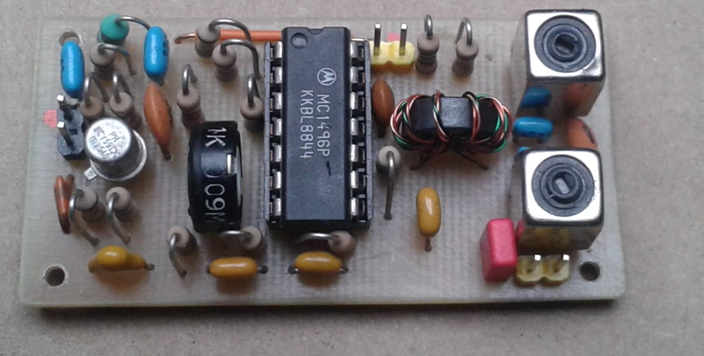
The board is very compact. Its dimensions are 50 by 28 mm (1.9 by 1.1 Inches).
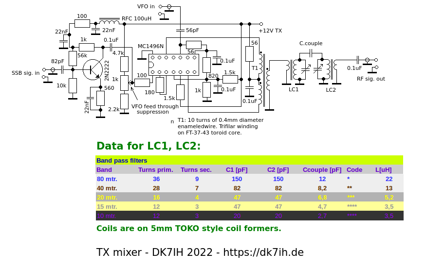
The Schematic
Starting from the left we see a preamplifier, then the potentiometer for minimizing VFO level at the output. This generally should not exceed 10mVpp. If it can’t be decreased below this certain signal level, it should be tried to reduce VFO input voltage, which should be kept in the range of 1.1 to 1.3 Vpp.
The mixer is terminated by a trfilar wound toroid to use the symmetric output of the IC. A bandfilter for the respective band follows to pass the desired frequency band and to filter the unwanted mixer products.
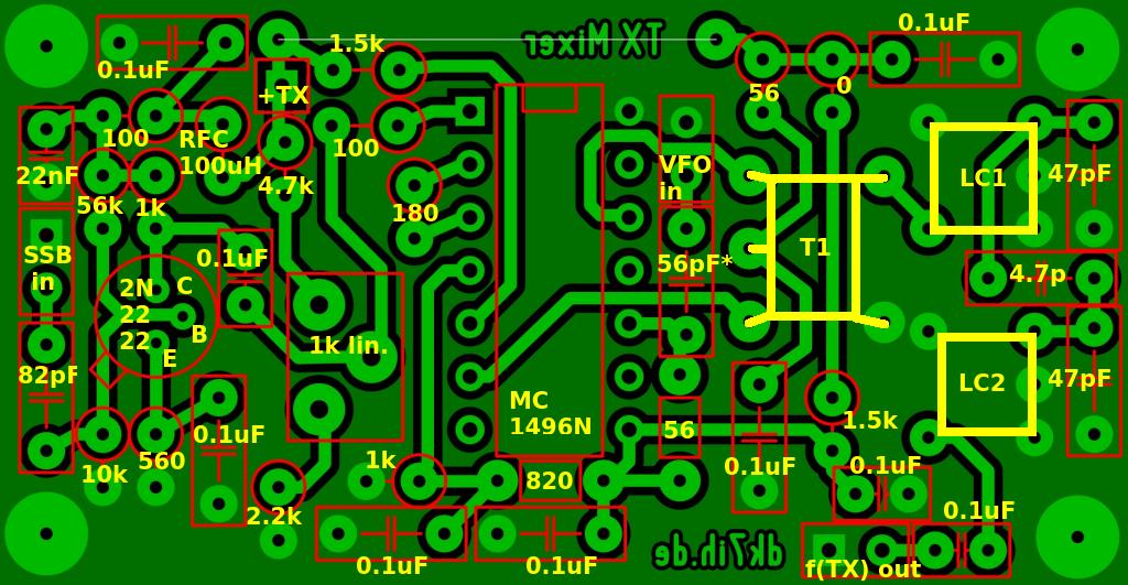
PCB and component placement
The PCB with its components:
Results
For testing the mixer a signal generator with 2 outputs is useful. One signal (representing the SSB input) is tuned to the desired interfrequency and set to an output voltage of approximately 0.2Vpp. The VFO representation (usually calculated by the formula: f.VFO = f.RX – interfrequency) should be in the range between 1.1 to 1.3Vpp. A signal with the desired output frequency should appear by the end of the band pass filter (BPF). When tuning of LC1 and LC2 is optimized the signal level here should be about 300mVpp.