A fellow radio amateur who visited my website gave me a hint for a very cheap module that is capable of generating rf sginals up to 200 MHz. It is the well-known Si5351A clock generator chip made by Silicon Labs (datasheet).It is available by ADAFRUIT mounted to a breakout board using 0.1″ conventional spacing. The chip itself is very small, so by using the ADAFRUIT stuff you don’t have to bother soldering SMDs to a PCB. (Link to ADAFRUIT). The chip is designed for 3.3V supply, on the Adafruit board you can find circuits to make this chip usable for 5V supply and 5V control lines. So it is compatible to standard 5V digital equipment.
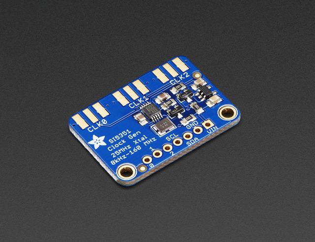
(Picture courtesy ADAFRUIT)
In contrast to the DDS chips I have been using before this one produces square waves. But especially for mixer purposes in a radio this can be an advantage because mixers generally are well controlled by square waves. And due to the mandatory page-mixer filtering circuitry harmonics are easily suppressed.
The Si5351 generator is intended to replace clock sources of all kinds, build PLL generators etc. It is fully programmable via I2C bus, in ATMega language called “TWI” (two wire interface).
My software does not use the Arduino code or other libraries, all TWI functions are written into the file to make understanding more easy without the neccessity to watch different files.
Basic guidelines for programming
Programming the Si5351 is a little bit more complicated than to set the frequency of the AD9xxxx DDS chips by Analog Devices that are well mentioned on my website. The programming of the PLL(s) and the synthesizer(s) is described in AN619 of SiLabs (Link). There are 2 steps to get the desired frequency out of the module.
Step 1: Set the PLL to a basic frequency (in my code to f=900 MHz)
Step 2: Divide this frequency using a “MultiSynth” divider to the desired output frequency using a set of equations given in AN619 and send this to one of the outputs (CLK0 to CLK2 with the Si5351A).
For handling step 1 you can see the function void si5351_start(void) in the code. Step 2 is done by the function void si5351_set_freq(int synth, unsigned long freq). Both functions look similar due to the fact that basic arithmetics do not differ very much. They got in common that you first have to calculate a set of integer values and subsequently write them into a larger number of registers of the Si5351. To understand this more easily I have written the register numbers into the code. It is highly recommended to watch the register table in AN619 to see the corresponding memory locations.
The software is very simple. You can generate one frequency that will be transferred to CLK0 output on the PCB. Watch the code:
/*****************************************************************/
/*             RF generator with Si5153 and ATMega8              */
/*  ************************************************************ */
/*  Mikrocontroller:  ATMEL AVR ATmega8, 8 MHz                   */
/*                                                               */
/*  Compiler:         GCC (GNU AVR C-Compiler)                   */
/*  Author:           Peter Rachow (DK7IH)                       */
/*  Last Change:      2017-FEB-23                                */
/*****************************************************************/
//Important:
//This is an absolute minimum software to generate a 10MHz signal with
//an ATMega8 and the SI5351 chip. Only one CLK0 and CLK1 are used
//to supply rf to RX and TX module seperately.

//I have tested this software with my RIGOL 100Mhz scope. Up to this
//frequency the Si5331 produced output.

//The software is more for educational purposes but can be modfied
//to get more stuff out of the chip.
//
//73 de Peter (DK7IH)

#include <inttypes.h>
#include <stdio.h>
#include <stdlib.h>
#include <math.h>

#include <avr/io.h>
#include <avr/interrupt.h>
#include <avr/sleep.h>
#include <avr/eeprom.h>
#include <util/delay.h>

/////////////////////
//Defines for Si5351
/////////////////////
#define SI5351_ADDRESS 0xC0 // 0b11000000 for my module. Others may vary! The 0x60 did NOT work with my module!

//Set of Si5351A register addresses
#define CLK_ENABLE_CONTROL       3
#define PLLX_SRC				15
#define CLK0_CONTROL            16
#define CLK1_CONTROL            17
#define CLK2_CONTROL            18
#define SYNTH_PLL_A             26
#define SYNTH_PLL_B             34
#define SYNTH_MS_0              42
#define SYNTH_MS_1              50
#define SYNTH_MS_2              58
#define PLL_RESET              177
#define XTAL_LOAD_CAP          183

//The unavoidable functional stuff
int main(void);
void wait_ms(int);

//  TWI Declarations
void twi_init(void);
void twi_start(void);
void twi_stop(void);
void twi_write(uint8_t u8data);
uint8_t twi_get_status(void);

//  SI5351 Declarations
void si5351_write(int, int);
void si5351_start(void);
void si5351_set_freq(int, unsigned long);

/////////////////////
//
//   TWI-Functions
//
/////////////////////
void twi_init(void)
{
    //set SCL to 400kHz
    TWSR = 0x00;
    TWBR = 0x0C;

    //enable TWI
    TWCR = (1<<TWEN);
}

//Send start signal
void twi_start(void)
{
    TWCR = (1<<TWINT)|(1<<TWSTA)|(1<<TWEN);
    while ((TWCR & (1<<TWINT)) == 0);
}

//send stop signal
void twi_stop(void)
{
    TWCR = (1<<TWINT)|(1<<TWSTO)|(1<<TWEN);
}

void twi_write(uint8_t u8data)
{
	TWDR = u8data;
    TWCR = (1<<TWINT)|(1<<TWEN);
    while ((TWCR & (1<<TWINT)) == 0);
}

////////////////////////////////
//
// Si5351A commands
//
///////////////////////////////
void si5351_write(int reg_addr, int reg_value)
{
   twi_start();
   twi_write(SI5351_ADDRESS);
   twi_write(reg_addr);
   twi_write(reg_value);
   twi_stop();
}

// Set PLLs (VCOs) to internal clock rate of 900 MHz
// Equation fVCO = fXTAL * (a+b/c) (=> AN619 p. 3
void si5351_start(void)
{
  unsigned long a, b, c;
  unsigned long p1, p2, p3;

  // Init clock chip
  si5351_write(XTAL_LOAD_CAP, 0xD2);      // Set crystal load capacitor to 10pF (default),
                                          // for bits 5:0 see also AN619 p. 60
  si5351_write(CLK_ENABLE_CONTROL, 0x00); // Enable all outputs
  si5351_write(CLK0_CONTROL, 0x0F);       // Set PLLA to CLK0, 8 mA output
  si5351_write(CLK1_CONTROL, 0x2F);       // Set PLLB to CLK1, 8 mA output
  si5351_write(CLK2_CONTROL, 0x2F);       // Set PLLB to CLK2, 8 mA output
  si5351_write(PLL_RESET, 0xA0);          // Reset PLLA and PLLB

  // Set VCOs of PLLA and PLLB to 900 MHz
  a = 36;           // Division factor 900/25 MHz
  b = 0;            // Numerator, sets b/c=0
  c = 1048575;      //Max. resolution, but irrelevant in this case (b=0)

  //Formula for splitting up the numbers to register data, see AN619
  p1 = 128 * a + (unsigned long) (128 * b / c) - 512;
  p2 = 128 * b - c * (unsigned long) (128 * b / c);
  p3  = c;

  //Write data to registers PLLA and PLLB so that both VCOs are set to 900MHz intermal freq
  si5351_write(SYNTH_PLL_A, 0xFF);
  si5351_write(SYNTH_PLL_A + 1, 0xFF);
  si5351_write(SYNTH_PLL_A + 2, (p1 & 0x00030000) >> 16);
  si5351_write(SYNTH_PLL_A + 3, (p1 & 0x0000FF00) >> 8);
  si5351_write(SYNTH_PLL_A + 4, (p1 & 0x000000FF));
  si5351_write(SYNTH_PLL_A + 5, 0xF0 | ((p2 & 0x000F0000) >> 16));
  si5351_write(SYNTH_PLL_A + 6, (p2 & 0x0000FF00) >> 8);
  si5351_write(SYNTH_PLL_A + 7, (p2 & 0x000000FF));

  si5351_write(SYNTH_PLL_B, 0xFF);
  si5351_write(SYNTH_PLL_B + 1, 0xFF);
  si5351_write(SYNTH_PLL_B + 2, (p1 & 0x00030000) >> 16);
  si5351_write(SYNTH_PLL_B + 3, (p1 & 0x0000FF00) >> 8);
  si5351_write(SYNTH_PLL_B + 4, (p1 & 0x000000FF));
  si5351_write(SYNTH_PLL_B + 5, 0xF0 | ((p2 & 0x000F0000) >> 16));
  si5351_write(SYNTH_PLL_B + 6, (p2 & 0x0000FF00) >> 8);
  si5351_write(SYNTH_PLL_B + 7, (p2 & 0x000000FF));

}

void si5351_set_freq(int synth, unsigned long freq)
{

  unsigned long  a, b, c = 1048575;
  unsigned long f_xtal = 25000000;
  double fdiv = (double) (f_xtal * 36) / freq; //division factor fvco/freq (will be integer part of a+b/c)
  double rm; //remainder
  unsigned long p1, p2, p3;

  a = (unsigned long) fdiv;
  rm = fdiv - a;  //(equiv. b/c)
  b = rm * c;
  p1  = 128 * a + (unsigned long) (128 * b / c) - 512;
  p2 = 128 * b - c * (unsigned long) (128 * b / c);
  p3 = c;

  //Write data to multisynth registers of synth n
  si5351_write(synth, 0xFF);      //1048757 MSB
  si5351_write(synth + 1, 0xFF);  //1048757 LSB
  si5351_write(synth + 2, (p1 & 0x00030000) >> 16);
  si5351_write(synth + 3, (p1 & 0x0000FF00) >> 8);
  si5351_write(synth + 4, (p1 & 0x000000FF));
  si5351_write(synth + 5, 0xF0 | ((p2 & 0x000F0000) >> 16));
  si5351_write(synth + 6, (p2 & 0x0000FF00) >> 8);
  si5351_write(synth + 7, (p2 & 0x000000FF));
}
/////////////////////////////////////////////
//              M  I  S  C
/////////////////////////////////////////////
//Substitute defective _delay_ms() function in delay.h
void wait_ms(int ms)
{
    int t1, t2;
    int dtime = (int) 137 * 8;

    for(t1 = 0; t1 < ms; t1++)
    {
        for(t2 = 0; t2 < dtime; t2++)
        {
            asm volatile ("nop" ::);
        }
    }
}

int main(void)
{
	unsigned long t1, freq = 10000000;
	PORTC = 0x30;//I²C-Bus lines: PC4=SDA, PC5=SCL

	twi_init();
	wait_ms(100);
	si5351_start();
	wait_ms(100);

	si5351_set_freq(SYNTH_MS_0, freq);
    wait_ms(5000);

    for(;;)
    {
		//Increase frequency in steps of 1kHz
	    for(t1 = 10000000; t1 < 10090000; t1+=1000)
	    {
			si5351_set_freq(SYNTH_MS_0, t1);
			wait_ms(1000);
		}
	}
    return 0;
}
I found lots of code for the Si5351 on the web, most of it much too long for my ideas. I reused some of the better parts and added some corrections and modification to fit my needs.
Some authors join the two functions (PLL definition and multisynth definitions) in the set_freq() function. I tried to avoid this because the code will be faster if you only set the PLLs once and afterwards just modify the frequency. Another idea that should be avoided is to switch off the PLLs during reprogramming the frequency. Unpleasant short-term absence of receiving signal is an outcome of the switch-off strategy. I leave the Pll running the whole time.
Thanks again for watching my amateur radio blog!
73 de Peter
Hi Peter.
I will test your strategy of setting the PLL once and then move only the multisynths, it makes a lot of sense doing it on this way.
Thanks for sharing the idea.
73 Pavel CO7WT
Changing only the mulitsynchs, and not the PLL forces you to use fractional divider values, which can generate a less clean output. As most people seem to be doing it this way, I am guessing that it’s not a problem.
One issue is that your code (and other examples I’ve seen), don’t have anyway to exactly calibrate the output to compensate for the EXACT frequency that the crystal is operating on. In my case, I was quite a few KHZ off frequency until I made use of the ‘fudge factor’ calibration value provided by the Arduino library I was using. There are two versions of this library out there, the newer one takes the frequency as an integer value based on a resolution of .01 hz, IOW, you must multiply your desired integer frequency by 100 to input to the library. I see your code is based on 1 hz resolution. I guess your example only shows a ‘scan’ function, no input for use as a VFO.
Just noticed something. I think you had to set the I2C address to 0x0C0 instead of 0x60 to indicate a write. You’d read from 0x60. I2C addresses are 7 bits anyway, not 8. The MSB is the R/W bit.
Nice article Peter!
Although somehow I observed a mistyping on the up to 20 bit maximum resolution p3 = c .
p3 should be 1048575d, (FFFFFh) all 20 bit high, instead the 1048757 (21 bit) that appears on text.
Thank your for your support.
73 JB KB5UWZ
Hi KB5UWZ,
thank you and you are absolutely right. I have received that hint before but somehow forgotten to change it. Now I have. Thanks again and 73 de Peter!
Dear Peter, I do not want to bother you. I am actually setting a Si5351a using assembly language on a PIC18F46K42. I not familiar with embedded C programming yet.
That way your routine calculating the Step 2 “MultiSynth” divider to the desired output frequency using a set of equations given in AN619, confuses me a little bit: unsigned long a, b, c = 1048575; unsigned long f_xtal = 25000000; double fdiv = (double) (f_xtal * 36) / freq; //division factor fvco/freq (will be integer part of a+b/c) double rm; //remainder unsigned long p1, p2, p3;
a = (unsigned long) fdiv; rm = fdiv – a; //(equiv. b/c) b = rm * c; p1 = 128 * a + (unsigned long) (128 * b / c) – 512; p2 = 128 * b – c * (unsigned long) (128 * b / c); p3 = c;I guess that although ‘a’ is defined as an unsigned long variable it is treated as an integer (INT(fdiv)). That way rm defined like fdiv – a would become the fdiv decimals. Correct?
I read an article indicating regarding the Si5351a indicating that the final frequency fo is equal to the PLL / (div + n/d)
where div can range from 4 to 900 n can range from 0 to 1,048,575 d can range from 1 to 1,048,575
I cannot figure out a direct relationship for these div, n and d parameters with the Output MultiSynth Registers MSx_P1 [17:0], MSx_P2 [19:0] & MSx_P3[19:0].
Or simply represent the unsigned long a, b, c variables in your routine ? So p1 =MSx_P1 [17:0], p2 = MSx_P2 [19:0] & p3 = c = MSx_P3[19:0] ???
73 JB KB5UWZ
Hi JB,
thanks a lot for your post, I will try to give some answers:
“fdiv” is a floating point number, generated by dividing the PLL frequency by the desired frequency.
When you say “That way rm defined like fdiv – a would become the fdiv decimals. Correct? ” you are right, “rm” stands for “remainder”.
The parameters a, b, c that are calculated by the set of equations (in AN619 referred to on p. 3) are then put into the registers of Si5351 by splitting them into the memory places. The problem: These memory places don’t have standard width like 16 bits (integer) or 32 bits (long integer). In this case you could just say “a goes to register 1, b into 2” and so on. Instead they have width of 17 and 19 bits or so. So, you have to “map” these odd bit width structures with “even” bit width structures of the numbers processed before.
Annotation: Don’t be confused that I have used long integers in places were int would have been enough. I have never cleaned the code so that it is very economical. 😉
The solution: The numbers calculated by the software (which have “standard” width like 16 or 32 bits) are thus converted by bitshifting and AND resp. OR compare into the “odd width” registers. This is some sort of “tayloring” binary patterns. That is done in the set of operations that you can find below the code line
“//Write data to multisynth registers of synth n”
I hope I got your question right and say
vy 73 de Peter (DK7IH)
Thank you for your support Peter,
I was not able to see a series of Si5351 initialization steps indicated on Si5351-B.PDF data sheet, 5.1. Writing a Custom Configuration to RAM, page 19. Figure 12. I2C Programming Procedure.
[Disable Outputs Set CLKx_DIS high; Reg. 3 = 0xFF, Powerdown all output drivers Reg. 16, 17, 18, 19, 20, 21, 22, 23 = 0x80, write new configuration to device using the contents of the register map
:Registers 15-92 and 149-170 and 183)].
Did I miss a give section in your simple to control the Si5351A clock generator chip software?
Reblogged this on eRDe and commented:
Habe gerade einige Breakout Boards SI5351 erhalten.
Unglaublich die Funktionsvielfalt.
Thank You Peter for your code. My name is Nahuel and im doing my final proyect of my course of study.
If I wanted to use fractional dividers.
How would I do it?
I would like to optimize the code.
Given an output frequency, which can calculate a, b and c.
How often do I have to assign the VCO?
I am confused by both equations of multisynth and pll. Both are similar.
I would like to create a 500 hz frequency modulated tone at 10.0 MHz
Or any value that’s simple
I am deep in the ether kit si5351, its great.I have CLK0 and CLK1 500 hz apart and it’s great listening on the sdr 50 cm away.
Is there a trivially obvious way right in front of me
Thanks, bradshaw K1te buzzards bay Massachusetts an hour south of Boston.
My ProgRock2 turns off its output on its first channel for 200 usec when turning off the second channel and turning on the third channel. That first channel serves as the reference oscillator for a PLL which then unlocks and doesn’t recover for a few tens of ms. Your comment towards the end of your article suggests that this might be avoidable. If changing an output frequency involves changing one of the PLLs, does that PLL shut itself down while it takes in its new instructions? Or can it run continuously and just shift to the new setting once its register is loaded?
Hello Halden, changing a PLL in the Si5351 always shuts down the respective PLL for a short time, at least what I could experience when examining the Si5351 clock oscillator. This might be caused by the resetting and relocking process when the PLL starts to operate under the new parameters. Thus I always have tried to avoid to reset the PLL when e. g. building a monoband transceiver. For multiband use I have reset the PLL but that has not been discernible as the whole band switching process around cut off the receiver for some milliseconds anyway.
Vy 73 de Peter