Abstract
A simple circuit to decode GPS/NMEA-Signals from a GPS-module will be discussed. The Software presented reads the $GPGLL message of a standard GSM breaktout module, decodes it and presents resulting data on an OLED display.
Basic considerations
GPS (Global positioning system) is a satellite based navigational system brought into operation in the 1990s and is operated by the US Pentagon. Since May 2000 it is also usable for civilian purposes by ensuring reduced accuracy to avoid military usage by non-authorized users. Currently there are 31 satellites in 6 different orbits. The system covers the vast majority of the surface of the earth except from polar regions. GPS signals are transmitted in the UHF spectrum labeled as “L1”, “L2”, and “L5”. Signals are coded on the basis of a mathematical algoirhtm. Precise positioning is possible when at least 4 satellites are visible to the user simultaneously.
For civilian usage off-the-shelf modules are available for very low prices. The provided accuracy can be estimated in the range of 10 meters.
The Hardware
This project consists of three low-cos components:
- An STM32F411 microcontroller (on a “Blackpill”-Board)
- A standard GPS module
- An OLED to visualize received GPS data
The circuit is very simple and does not contain any complexity:
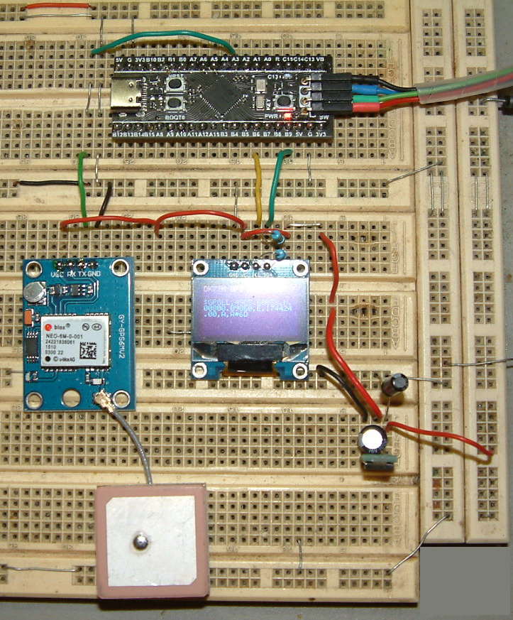
The OLED is connected via an I2C interface (PB6=SCK, PB9=SDA) to the MCU, the GPS module uses only the “TX” output of the GPS receiver which is fed into PA3 which represents USART2 input in the STM32F411 microcontroller.
The Software
As usual the code has been written in “Embedded C” using the GNU ARM compiler toolchain. The C-file can be downloaded from my Github repo.
The code first ensures exact clocking because the USART’s baudrate depends on the clock frequency. The given calculation hints and formula by STM are
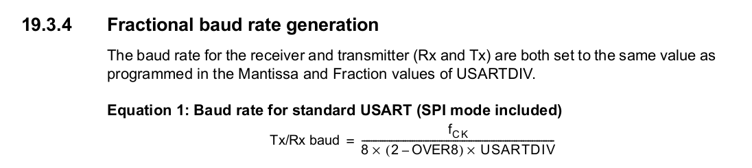
“OVER8” is an overclocking factor that becomes 0 when USART is used in standard mode. When knowing the projected baud rate, the formula has to be converted to calculate USARTDIV.
USARTDIV = fCk / (16 * baudrate)
USARTDIV results in a fractional number where mantissa and fraction will be put into the respective register, the so-called BRR (baud rate register):
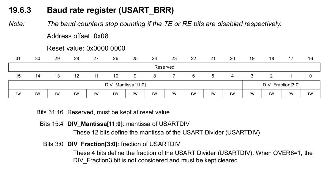
The fractional part is represented by bits 3..0. It has to be multiplied by 16 before being written into the register. Bits 15..4 are the mantissa part.
Example:
Given a projected baud rate of 19200 and a CPU clock frequency of 50MHz for USARTDIV we calculate a value of 162.76. Mantissa therefore is 162 and fraction is .76. This multiplied by 4 results in 3.04. Thus we write 162 into bits 15..4 and 3 into bits 3..0.
Decoding GPS data
GPS data is coded as so-called NMEA strings. There are various of these string, each containing different sets of information. Every string commences with a “$” character followed by a 5 letter code.
Example: $GPGLL contains the current geographic position defined by latitude and longitude and time in UTC. It can look like this
$GPGLL,4907.0013414,N,11402.3279144,W,205412.00,A,A*73
The data are comma separated, the whole string is terminated by a “*” character and by a checksum. All strings are finally ended by a CR/LF sequence which can be used to indicate completed transmission. As this specific string keeps all the information we need for this project it is the only one to be decoded.
Data is transmitted once per second. An interrupt is called whenever a character is received. The received characters are fed into an array of chars and processed to the OLED as soon as the LF character has been detected.
Vy 73 de Peter