by Peter Baier (DK7IH)
Abstract
Dual audio tone modulation is a standard method for testing linearity of single sideband transmitters. Usually 2 analog audio oscillators are used. Their frequency must not be harmonically related. A suitable set of frequencies would be 700 and 1700 Hz for example. With this project instead using analog oscillators a method of generating the two audio frequencies by the means of DDS will be described. The dual audio frequency generator is setup from standard modules:
- Microcontroller (MCU): STM32F4
- LCD: 2×16 characters DOT matrix LCD
- DDS: AD9850
- EEPROM: 24C65
Circuit
This project uses only off-the-shelf modules and hence should be no problem to build. The wiring diagram thus is kept relatively simple:
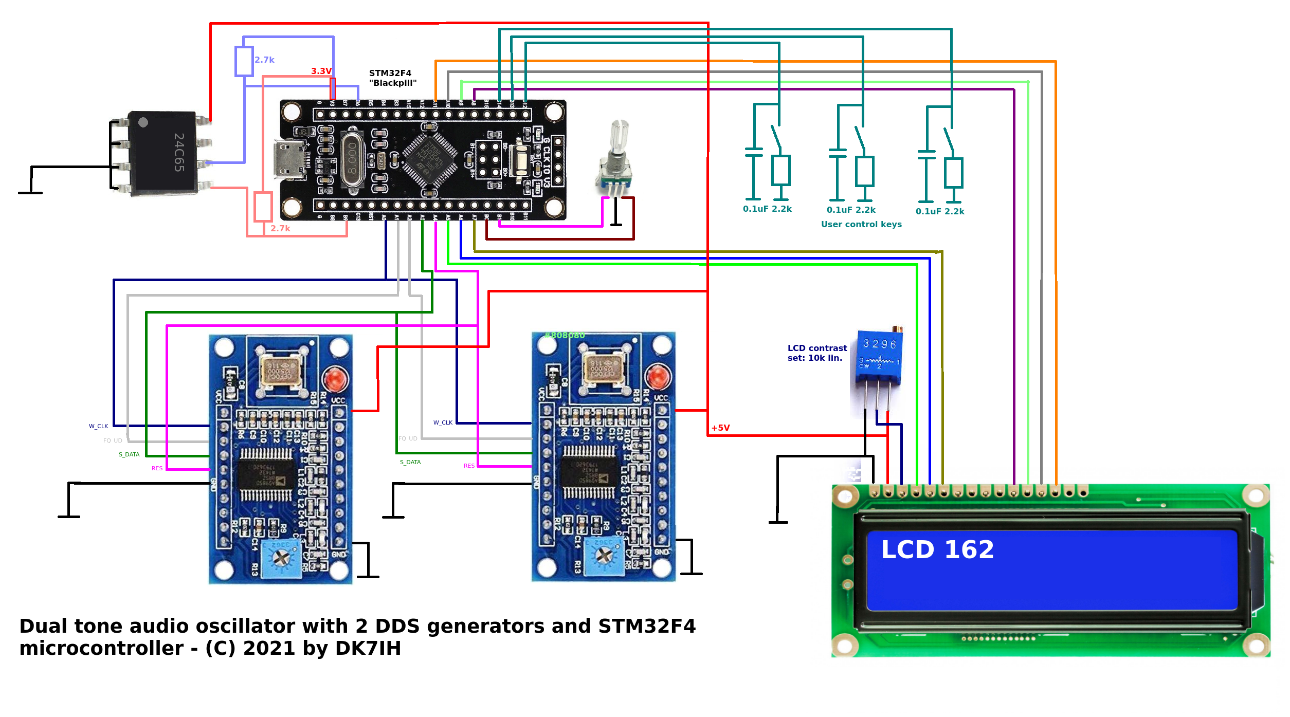
(Click for full size image)
There are 2 DDS modules (AD9850) that are available from Chinese suppliers for competitive prices. They are clocked with 125 MHz external clock thus being able for frequency generation up to 40MHz. In this project they are some sort of “overkill” because only audio frequencies will be generated. Generally this circuit could be modified to produce 2 frequencies in the rf range and driving a transmitter directly on the output frequency without the need for an audio modulator.
The MCU used is an STM32F411 on a so-called “Blackpill” board. It is clocked by software setting with 100MHz which is very much suffice for this simple layout. The MCU is a 3.3 V type but the input and output ports of the STM32F4 are 5V-tolerant. As the MCU does not have internal EEPROM (which AVRs e. g. have) an external 24C65 EEPROM IC has been connected via the I2C bus. There are also some software solutions to emulate EEPROM for the STM32F4 by using flash memory but that was not our intention.
The LCD is a standard DOT matrix 2 line display.
Frequency set for the 2 channels is done by a rotary encoder. 3 user keys define either if channel 1 or channel 2 is affected by frequency adjustment. A third key save the current frequency setting to EEPROM to be reloaded when the device is switched on again.
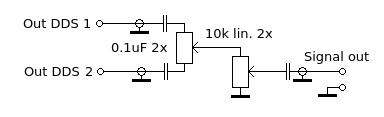
Audio output
The 2 sine wave output ports (marked as “Sine Wave Out 2”) of the 2 DDS modules are fed into a balance potentiometer which is succeeded by a volume control variable resistor. All lines must be shielded to avoid rf coupling in to the audio signal. Sine wave output is about 0.7 Vpp. which is sufficient for driving the microphone input of an SSB transmitter.
Results
With this device a more exact definition and variation of the two audio frequencies is possible. Thus transmitter adjustment is made easier and more precise.
Software
As usual the code for this project is stored on my Github Repo.
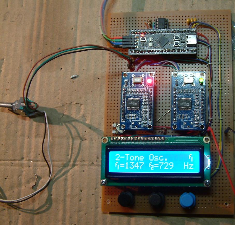
The prototype on my workbench: