This device is as simple as useful. With 2 transistors and an oscilloscope it is fairly easy to test the linearity of your SSB transmitter. The 2-tone-method is a standarized test method that can be used to determine the maximum output and the amplification characteristics of a sideband transmitter.
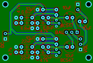
Just a hint before you read on… I have designed a PCB (Through-hole technology) for this circuit (50 by 30 millimeters, about 2 by 1.25 inches) that can be purchased via my new QRP online shop:
Visit DK7IH QRP-Shop
The method involves 2 audio tones simultaneously applied to the microphone input of the DUT (device under test). The two frequencies must not be harmonically related and must both fall within the audio passband of the transmitter. Also they should have a significant spacing in the audio spectrum. 850 Hz and 2200 Hz are a good choice, for example. If you own a spectrum analyzer with an appropriate resolution the Third Order Intermodulation products (IM3) can also be made visible. I’ll refer to that in a later page, today we want to talk about the amplitude side only.
First, here’s the circuit:

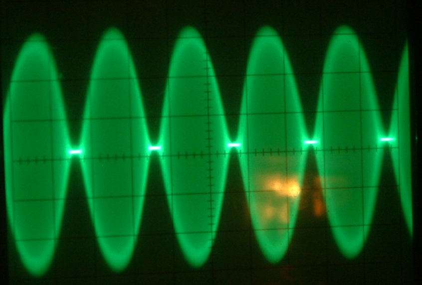
The heart of the device are two oscillators producing 2 sine waves which generate a new waveform that is formed by superposition of the 2 single signals. It resembles an amplitude modulated carrier and should look like this when displayed with an oscilloscope:
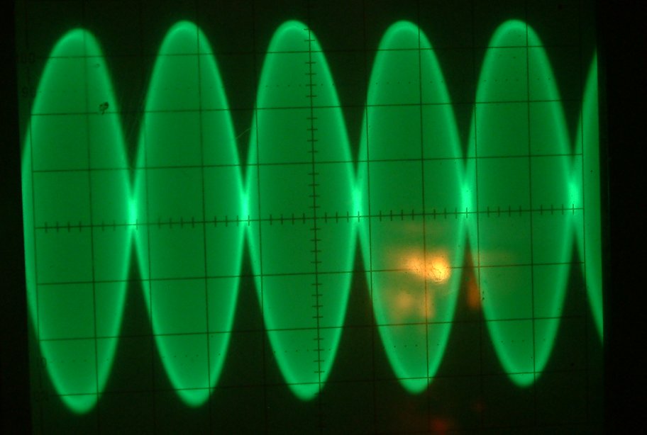
The “balance” of the tone generator circuit must be carefully adjusted to regulate the amplitudes of the two audio signals in a manner that the cross section centering the waveform is as sharp as possible. Then the two audio signals are nearly 100% equal which will result in the demonstrated signal amplitude waveform.
Wrong adjustments of the transmitter can be easily observed like the following pictures show. First one is an amplifier that is overdriven:
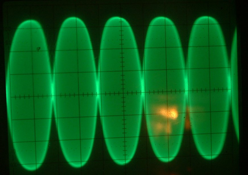
This is a sample of the classical “flat topping”. At least one amplifier stage in the exciter is running in saturated mode thus not being able to deliver proper amplification of the signal’s higher amplitudes. The transmitter will sound very distorted. Also a high set of IM3 products will appear thus make your signal much wider than acceptable.
The following picture shows an SSB amplifier running with inadequate bias setting:
The bias in this case is much too low so that lower voltage areas of the amplitude are not amplified sufficiently. Bias setting must be increased to ensure proper amplification.
To measure the peak output of your transceiver you can either use the amplitude reading of your oscilloscope. Divide the peak-to-peak voltage by 2.81 (two times the square root of 2) to convert p.-p- voltage to effective voltage, square it and the divide the result by your 50 ohm resistive load.
Veff. = Vpp. / 2.81 (I)
P = Veff.² / R (II)
Or you use a VTVM (valve tube voltmeter) with an RF probe that gives you an RMS reading of the transmitter’s output voltage.
Keep in mind: The power you’ll get is half of the peak output power of your transmitter!
If you managed calculus, then it’s quite clear why. 😉
73 de Peter!
Does not say what size coax to use on this project,and what is good for inside of radios.
Hi,
concerning coax: Any shielded cable for audio purposes is sufficient. And I would not build it inside a radio. It’s a piece of test equipment.
If I were to use 2N2222 transistors, what changes would I need to make?
Hi Dave,
you can use a 2N2222 instead of a BC547 like any other AF transistor. 73 de Peter
The oscillators aren’t Wien Bridge. They are phase shift oscillators.
Are the resistors labeled 4k7 meant to be 4.7k or 47k?
Hi,
“4k7” means 4700 Ohms. In general “k” or “M” etc. are the decimal seperators.
Vy 73 de Peter (DK7IH)
Hello Peter,
Do you also have a print board layout available?
73 Nat
No, sorry to say that I don’t have printed layouts. 73 de Peter
HI Peter was the print board layout provided by Szilard published anywhere for download?
Cheers
Andrew
I have made with Sprint layout, if you want, I can send it to you
Hi Szilard, if it is for public domain I’d put it only with you named as author? 73 de Peter
Hi Szilard.
If you still have the Sprint, I am interested in it. It is only fo me.
Hi, I was wondering, since capacitor type is not specified other than the electrolytics, if ceramic capacitors could be used for the 6.8 and 22 nF ones? Thank you.
Hello Jon,
yes, you can use ceramic caps without any problems. Frequency stability is no problem due to the low audio frequencies generated.
73 de Peter
Hi Peter,
Thanks for responding so fast. That definitely tackles my junk box only having ceramics, but brings up another issue:
I only have the 22 nF ceramics and none of the 6.8 nF. I assume I could change the frequency by changing some of the resistors. I have 6 of the 22 nF, what resistors would I change and to what value to get the frequency that would have been produced with the 6.8 nF?
Thanks again!
So, how would I go about changing the frequency of one of the oscillators to something like 1 Khz instead?
Hi, that is a matter of try and check. If you increase C and R the frequency decreases and vice versa. But there is no 100% linear function. I suggest trying it on a breadboard and then get the best values out of it.
vy 73 de Peter
Good day Peter, i would like to ask where do i connect the output signal, directly to the mike or through a empty microphone plug, please be patient as i am new to electronics , i do have a 20mhz Chinese pc oscilloscope a wattmeter and digital voltmeter ,as the finals are burnt in my radio ,i’m waiting for arrival ,so in the mean time i could build this circuit ,because i don’t have a 2 tone signal generator ,thankyou for sharing this project i greatly appreciate it, greetings from nico Italy
Hi Nicolo, you can connect the output of the generator to a microphone plug for the radio you want to test. I receommend using a series resistor of 2.2k (for decoupling the radio from the generator) and a parallel capacitor 0,01uF (10nF) to GND to avoid rf stray energy intruding into the radio. That works fine for my homemade radios and it should also work with commercial ones.
vy 73 de Peter
I just built this. Had a bit of trouble getting it working because I had mistakenly hooked one of the base bias resistors to the plus supply instead of the collector of the transistor. Nope, that doesn’t work. It will NOT oscillate unless that 150K is connected collector-to-base.
I only used one 10uF bypass. The transistors are close together, and it’s a low frequency circuit. Didn’t see the need for a second one.
I needed the oscillator to test a homebrew linear amplifier. I do have a Heathkit SB610 monitor scope that has a two-tone oscillator – but only one of the tones works. Interestingly,
the SB610 has pretty much exactly the same circuit – except the two transistors are tubes. Actually sections of a 6J11 dual pentode. And the phase shift networks are encapsulated in ceramic.
Hi Jerry,
thanks a lot for your reply. Yes, the circuit sometimes might be a little bit “reluctant” to oscillate. This is because the relation of C and Rs is a little bit “strange” to set the desired frequency. That is one of the reasons that I have developed a digital equivalent ( https://dk7ih.de/a-dual-audio-frequency-generator-with-2-dds-modules/ ) where frequncies can be very exactly adjusted.
vy 73 de Peter (DK7IH)
Two questions:
(1) Would the circuit work equally with a +5 VDC regulator at the input? Just curious on this.
(2) Would it be practical to power the regulator from a standard 9 V alkaline battery? Or would there be too much current drain to have the battery last a usable length of time? I’m just thinking of making the unit self-contained.
Hi Dean,
The answers for your questions:
a) I think 5V (stabilized) should be OK, too. Maybe the frequencies will change slightly.
b) Yes, the 9V are high enough with the integrated 6V regulator so that the voltage drop will not cause any problems. If necessary a low-drop voltage regulator can be installed on request.
Vy 73 de Peter (DK7IH)
I wish to make this two tone generator. I have all the stuff except for the regulator, but…. In looking at the schematic, there is no connection shown to the 78L06 regulator ground/common connection. Is this ground reference not needed? Interesting….
Hi Phil, thanks a lot for your hint. My fault, the picture has just been corrected. Vy 73 de Peter