This 6-band transceiver has several stages where band switching will occur:
- The band pass filter section (shared by transmitter and receiver)
- A first section of low pass filters (LPF) between the driver stage and the final amplifier
- A second section of LPFs at the end of the rf power amplifier chain.
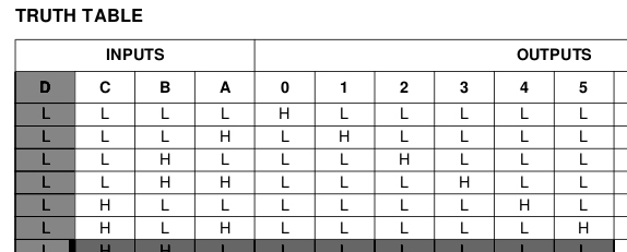
To keep the circuit simple and to save controller output ports I have decided to code the band number (0 for 160m up to 5 for 10m) in binary and send this pattern to pins PA0:PA2 of the MUC. This is pattern is lead to a BCD to Decimal Decoder integrated circuit (HCF4028) that converts the binary pattern to a set of individual output lines. The respective part of the truth table used is:
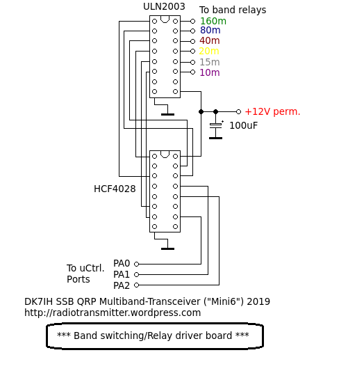
The 6 lines are fed into an ULN2003 integrated circuit, which is a relay and motor driver.
The outputs of this driver are switched against GND thus the relay coils have to be supplied with VDD (+12V in this case). The IC also contains a clamp diode for each output. That makes the circuit fairly simple. The full circuit of this unit:
Peter, do you control all 3 relays from the one ULN2003 ? If so, that is simpler than the 2N7000 FETs I’ve used as relay switches. One thing, how does this IC behave at power on, do some or all of the outputs momentarily go low? In which case, the relays would pull in for a moment. Not unacceptable but useful to know.
Paul VK3HN.
Hi Paul,
the ULN2003 allows a max. Ic of 500mA. As I use only one channel by time and the relays have a coil resistance of 1kOhm (and I am using 4 relays per channel including 2 additional ones in the bandfilter section) this is much within the region of safe operation (Ic total = abt. 50 mA)
Second: When I power up the rig, the outputs are set to high, so they don’t have high resistance and the relays therefore are not active. Also no problem!
To come to a conclusion: The ULN2003 is a fine choice if you want to have simple circuitry for a driver module.
Vy 73 de Peter.