This article describes the “Cigarette Pack” SSB QRP transceiver” for 14MHz that I first had mentioned some months before. Recently, when taking it from the shelf, the transceiver dropped to the floor and was severely damaged. This lead to serious defects in the front panel area, the main frame, the cabinet and so on. The interior parts were, luckily, not affected by the crash. So, I had to revise the whole radio, make a new front panel and cabinet, ply the frame straightly (as far as possible) and so on. This is the full description of the rig now to complete the files here. The good news: The radio is fine again and fully operational! And the even better news: I still have not started smoking! ![]()
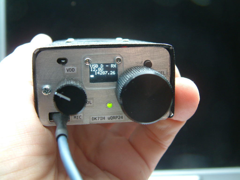
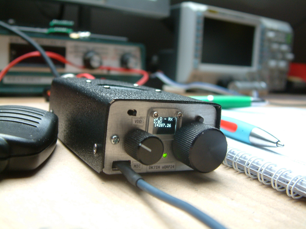
During reconstruction the transceiver has been extended for about 5 mm so that overall length now is 100mm (3.9 inch). This was done because I intended to build in a loudspeaker. The other dimensions remain unchanged: Width is 52mm (2 inch.), height is 30mm (1.2inch). OK it is slightly longer now than a standard pack of cancer sticks, but who cares? Total cabinet volume is 150cm³.
Basic concept
The transceiver is based on the “Micro 23” rig, that I have described here. Some simplifications of that already simplified radio have been made. Here is the full schematic of this even smaller transceiver:
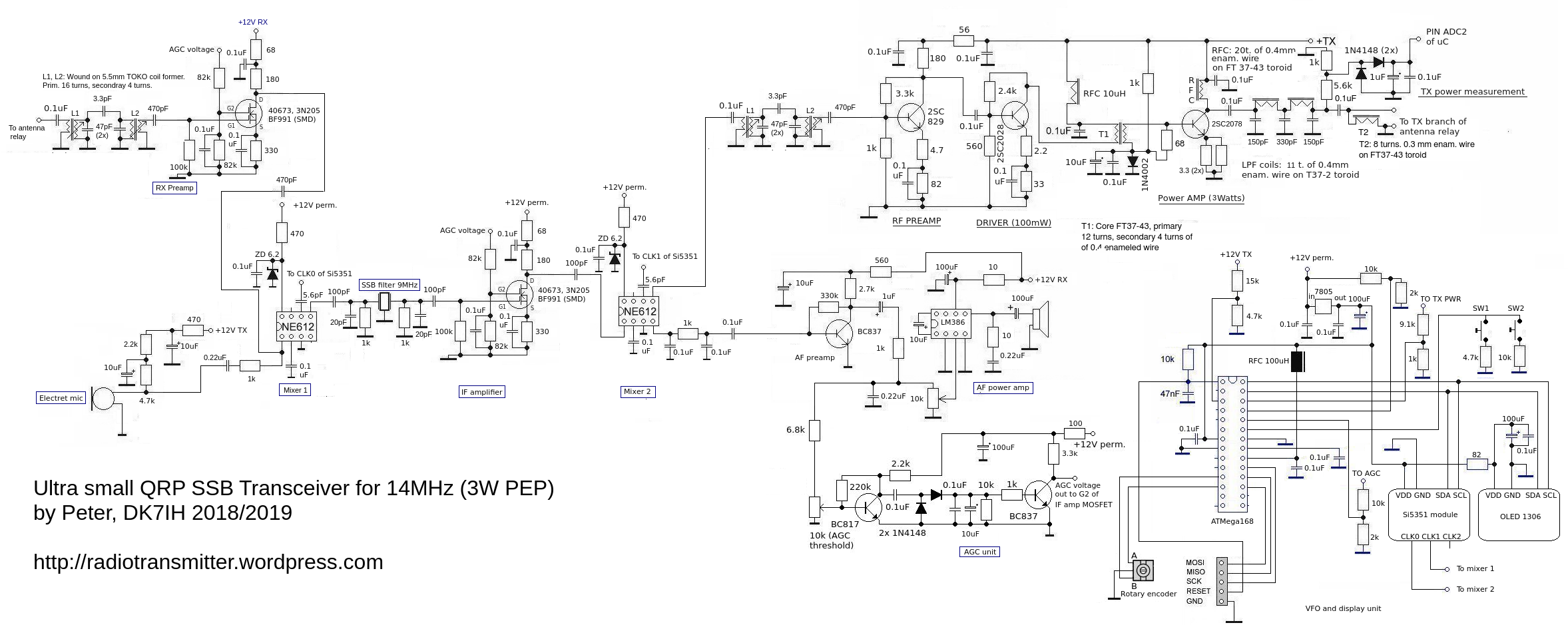
Very simple rigs like this one always use parts of the circuit for receive and transmit purpose. Here these parts are the 2 mixers (NE602), the SSB-filter and the interfrequency amplifier.
Signal flow schematic
The NE602 has a balanced output. With mixer 1 only one of them is used. If higher gain is desired, a broadband (or even better a tuned LC circuit) transformer could be used to connect pin 4 and 5 (the mixer outputs) in push-pull mode. I did not do that to save the transformer.
The signal flow can be derived from the design:
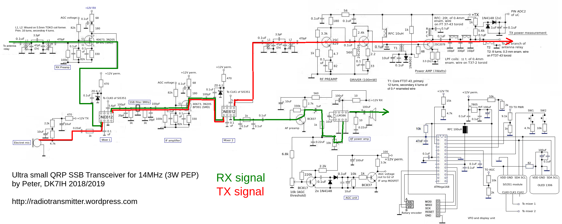
Receive mode signal flow
From the antenna relay (not drawn) the rf energy runs through a 2 pole LC filter for 14 MHz. The coils are wound small TOKO coil formers, all respective data is given in the schematic. Coupling is loose via a 3.3pF cap.
NExt stage is an rf preamp for 14MHz with a broadband output. The acitve element here is a dual-gate MOSFET.
After having left this stage the 14MHz signal travels through another 470pF capacitor. This one has high resistance for audio frequency and low for rf frequencies due to the equation: XC =1/(2*PI*f*C). The signal is then fed, together with the audio signal from the microphone (when on transmit), into mixer 1 input on pin 1. The 1k resistor prevents the rf energy from flowing into the microphone circuit. The two signals are separated from each other by simply exploiting reactance and resistance in a rather clever way 😉.
When receiving the Si5351A clock chip is programmed in a way that the VFO signal (23 MHz) is present on output CLK0. It is fed into mixer 1 via a small cap to prevent overloading of the mixer. The Si5351A breakout board delivers about 3 Vpp. clock signal, so this must be reduced to about 200mVpp. A 5.6pF capacitor is OK here.
The resulting signal is sent to the SSB filter (a 9MXF24D) that is terminated with 1kOhm and 20pF in parallel. The wanted SSB signal is present at the output of the filter.
Next stage is the interfrequency amplifier, equipped with a dual-gate-MOSFET semiconductor. This one is connected to the AGC chain, on receive a variable voltage is applied to gate 2 (range 0 to 6 V), on transmit the AGC is fully powered to ensure maximum gain.
Next is mixer 2 which is the product detector when receiving. The signal (9MHz +/- sideband shift) is applied to pin 6. Due to the fact that this mixer also serves as transmit mixer, the two signals are taken from the two mixer outputs on pin 4 (serving as audio output) and pin 5 (serving as rf output for transmitting).
Two audio amplifiers (preamplifier and power stage) give a sufficient signal level for an 8 ohm loudspeaker or a headphone.
For the loudspeaker I tried out the tiny ones for smartphones with good success. Only the volume was a little bit low. Then I found another speaker in an old toy of my daughter that turned out to be very much OK for this transceiver. Its diameter is about 3 cm (1.2 inch) and just fits in the housing.
Transmit signal flow
The microphone in this radio is an electret one. The advantage is that these microphones have an internal preamplifier equipped with a field-effect-transistor. The output voltage is fairly high, about 1Vpp. when normally speaking into it. Therefore an audio preamp is obsolete. The microphone signal is directly fed into pin 1 of the first mixer. On transmit the Si5351 signal generator is switched that the 9MHz (+/- sideband shift) signal is fed into pin 6. The SSB filter eliminates the unwanted sideband, the interfrequency amplifier lifts the SSB signal to an appropriate level. The TX mixer is fed with the 23MHz signal resulting in a 14 and 37 MHz signal. The TX band pass filter cleans the signal from the unwanted 37MHz component resulting from the mixer process.
RF power amplifier
The power amplifier is a 3 stage circuit. Stage 1 (preamplifier) brings the signal to about 10 mW. This is coupled into the driver stage via a cap of 0.1uF without any further impedance matching.
The subsequent driver stage shifts the signal level to about 200mW. Linear amplification is ensured her (as well as in the previous stage) by negative feedback in the collector circuit and emitter degeneration with a non-bypassed resistor to GND. An output transformer (winding rate 4:1, impedance rate thus 16:1) lowers the impedance of some 100 ohms to a few 10 ohms present on the input of the final amplifier stage.
The final amplifier brings up a signal level of 3 to 4 Watts PEP. This stage is in AB mode, the appropriate bias is achieved by the 1k resistor going to +12V TX and the current to GND via the silicon diode. This diode must be thermally connectod to the final transistor to stabilize the bias.When the transistor heats up, the silicon diode increases the current through it thus decreasing bias to the transistor.
The 68 ohm resistors serves 2 purposes: First it prevents the input signal from being shorted by the bypass caps in the bias circuit and it stabilizes the rf behavior of the stage by limiting the gain because certain amounts of the input power are led to GND. This prevents self-oscillation.
DC ad the collector is fed through a radio frequency choke to hinder rf from flowing into the DC line. Radio frequency is directly fed into the low-pass-filter. The output impedance of this stage is roughly 50 Ohms, so the filter can be a 50 ohm circuit with a cutoff frequency slightly above 14MHz.
The VFO section
The Si5351A clock chip used here has three frequency outputs that can be set individually. Only CLK0 and CLK1 are used in this radio. The Si5351A chip is programmed by software in the following manner:
- Receive: CLK0 is the VFO, CLK1 is the BFO.
- Transmit: CLK0 is the BFO, CLK1 is the VFO.
The microcontroller reads the tx/rx status and switches the frequencies respectively.
Construction
The radio is a full SMD design on a 0.1″ pitch double sided Veroboard:
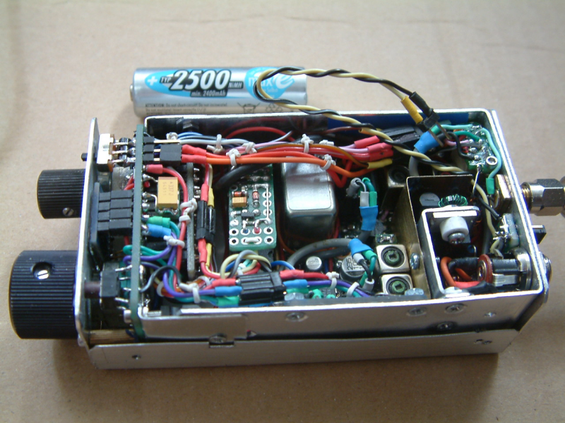
The control panel on the left with tuning knob and volume set. The 64×32 pixel OLED between these controls. Following the microcontroller behind the fron panel (here covered). The controller is an ATmega168 on an Arduino Pro mini board.
The isolated board left of the SSB is the AGC section. The receiver and transmitter shared parts follow, the TX band pass filter is in the foreground. The power transmitter is on the right behind the shield. The shield is necessary to avoid unwanted oscillations when rf is coming back from the power transmitter to the band pass filter prior to the tx section.
On the right there is the SMA socket for connecting the antenna plus a 3 pin header for connecting a headphone. When there is no headphone in use a jumper connects the internal speaker to the speaker line. VDD is applied via a standard DC connector.
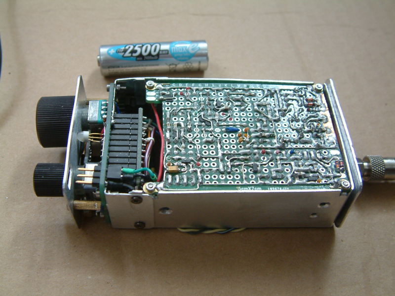
The underside of the board has only some SMD components and the wiring on it:
“On the air”
My longest distance achieved with this transceiver (after rebuilding it) has been R2DLS near Moscow who gave me a “59”-report. ![]() The antenna in use is, as always, a Deltaloop.
The antenna in use is, as always, a Deltaloop.
73 and thanks for reading this article!
Peter (DK7IH)
Peter, you have really mastered ‘compact construction’ using readily available parts and hand assembly. You might call it ‘radio drafting’, and there is a lot of design and sketching in it, but I call it ‘radio craftsmanship’, in the tradition of the great work of the Arts and Crafts movement, in which the designing was inseparable from the making. Fine business.
As you know I built your Micro42 design which has similarities to this circuit, although it doesn’t reverse the VFO and BFO between receive and transmit. In my little rig I added an additional BF991 IF gain stage (one either side of the filter), a low gain MFE131 RF amp after the BPF, and a louder audio amp (TDA2003). Also an IRF510 PA. Otherwise, it is your Micro42 design. It works well — very sensitive, lots of gain, strong AGC, and excellent carrier suppression. I have no issue with strong signal overload. A week ago, while operating portable, I was able to work VK3 to KA6 with its 5 watts CW. Thanks for refining these ultra simple transceiver designs.
DK7IH> Then I found another speaker in an old toy of my daughter that was very much OK for this transceiver.
Repurposing parts is part of the creativity and fun of making. I’m now on the lookout for discarded children’s toys on my neighbourhood rubbish piles!
73 Paul VK3HN.
Hallo Peter,
Deine Projekte, die ich schon seit Jahren verfolge, finde ich toll. Bei Deinem letzten Proekt habe ich Probleme mit den Bandpassfiltern. Ich gehe davon aus, dass im Schaltplan bei den Spulen links primär und rechts sekundär entspricht. Liege ich richtig?
Ich wünsche ein schönes Wochenende.
73 de Uli / DF7IY
Hallo Uli, die Schaltbilder der Bandpassfilter sind so zu lesen, dass die “kleine” Spule im Schaltbild immer jene ist, die nur 1/4 der Windungszahlen der “großen” hat. D. h. sowohl der Ein- als auch der Ausgang sind die Koppelspulen mit der niedrigen Windungszahl. Die jeweils den Koppelwindungen gegenüberliegenden Spulen sind dann jene für die abgestimmten Kreise mit der 4-fachen Windungszahl der Ankoppelwindung. Im Grunde ist die Anordnung also immer spiegelbildlich zu sehen. Ich hoffe, ich konnte das jetzt einigermaßen verständlich erklären. 😉
vy 73 de Peter
Hi Peter. Nice job you do.
I have a about similar idea, and i build a “tea box” transceiver” (see my QRZ.com page for a little more info). This seems as small as your design, but for the 40M band.
Anyway, nice to see some active builders on the web.
Best 73’s,
Didier (ON4KDV).
Hi Didier, thanks for the link to the “Tea Box TRX”. That looks very nice! Congratulations. Is there a schematic anywhere? 73 de Peter (DK7IH)
This is such a great build. Your tiny construction work is amazing. My Arduino boards look like utter shit. Are you using a tiny soldering tip there? I get solder all over other holes :/
Stuff on the blog if you fancy a laugh…
Hi Mark, no, I use a tip with 2 millimeters width at the top of the tip. Heat conductivity is much better compared to those pencil-shaped ones. Always have it in top clean condition! vy 73 de Peter (DK7IH)
Can this be purchased pre-built and tested? Would be very interested in use in my car while driving – no distraction, just tune around and talk.
Hello Scott, sorry to say that I don’t sell kits, boards or other stuff. The rigs I build are just for more or less “academic” practise. 😉
Vy 73 de Peter (DK7IH)
Congratulations. Very nice and tidy work, all in it´s place and seems to be working very well. Don´t loose the homebrew spirit. Ham Radio needs people like you to show the newcommers that radio can be done with homemade equipments. I will show this article tou our HamRadio Club – Youth Department.
73 de CT1DOV
John in IM58LU
Thanks a lot, John, very much appreciated! 🙂 73 de Peter (DK7IH)
Hola Peter, Tengo una duda con respecto a L1 y L2, los primarios son los que tienen 47 Pf en paralelo al bobinado? Gracias y lo Admiro por sus trabajos!!! Mis Respetuosos Saludos. LW3EXC Walter desde Argentina
Hola Walter, sorry, my Spanish is not that strong, so I answer in English… 🙂
To sum things up: I use these TOKO style coil formers with a primary and and a secondary winding. The “primary” here is 16 turns which is paralleled by a 47pF cap covering the 14MHz-band. The secondary is 4 turns. The band-pass filter (BPF) is coupled in via the “secondary” of L1 (which in fact is the “primary” in this case due to the reverse placement of the coil). The 16 turns part always is the tuned circuit (together with the parallel cap) whereas the 4 turns coil is for in- respectively outcoupling the rf energy from the BPF.
BTW: Sometimes I modify this circuit a little bit and the incoupling is done by a small cap (in the range of 6.8 to 12 pF) directly to the “hot” end of L1 tuned circuit. But in this transceiver I have used the secondary turns with both coils.
Hope that helps a bit…
Vy 73 de Peter (DK7IH)
Muchas Gracias Peter!!! Estoy comenzando con la construcción, disculpe Hablo poco Ingles, pero para leer me es facil.
Lo Admiro!!! y sigo todos sus trabajos. Desde hace tiempo quiero hacer este equipo. GRACIAS!!! Saludos y respetos..Walter
Where can I buy one?
Hello Richard, a kit is currently under construction an will be released in August. VY 73 de Peter
Thank you so much for posting the schematic. I have built a hacked version of the cigarette transceiver using the micro26 code from your github with some modification for the vfo frequency code. I still have some tweaks to make. For the filters, I used the rf-tools bandpass calculator to make bandpass filters (50 ohm + matching transformer for receive and ~1000 ohm before the transmit amplifiers). I needed a nanovna to make sure they worked though. Instead of a dual gate mosfet, I used a jfet cascoded with a bjt, but the bias needed adjusted. I’m not sure it works as well as the dual gate. I still need to get the AGC working, probably because I used 3906 and 3904 transistors almost everywhere :-/. I have just made my first several contacts from 700-1200 km away. I need to document the build so I know what the circuits look like. I did use the SSB filter from FunkAmateur, and I somehow navigated the German. This is my first non-kit radio build, and it’s all throughole stuff, so it’s a really ugly baby. This was the most difficult electronics project I’ve ever done (all the substitutions probably), so I’m so happy to have finished (except the AGC and documentation). I know so much more now about being a ham. Again, thanks so much for documenting your journeys, and progressing the ham culture. You have amazing design and build skills.
Hello Riley, thanks a lot for your entry. Congratulations on the successful completion of the transceiver. Like to hear that. If you like, you can send me some picture so that I can have a look on the “ugly” construction. 😉
Keep on homebrewing!
Vy 73 de Peter (DK7IH)