Having deferred the work on the “micro multibander” for some time I finished another small QRP rig (this one for 7MHz) that is suitable for my summer excursions by bike or hiking the local mountains here in the State of Rhineland-Palatinate or the Black Forest that is not that far away on the other side of the Rhine valley.
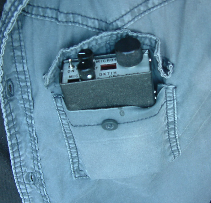
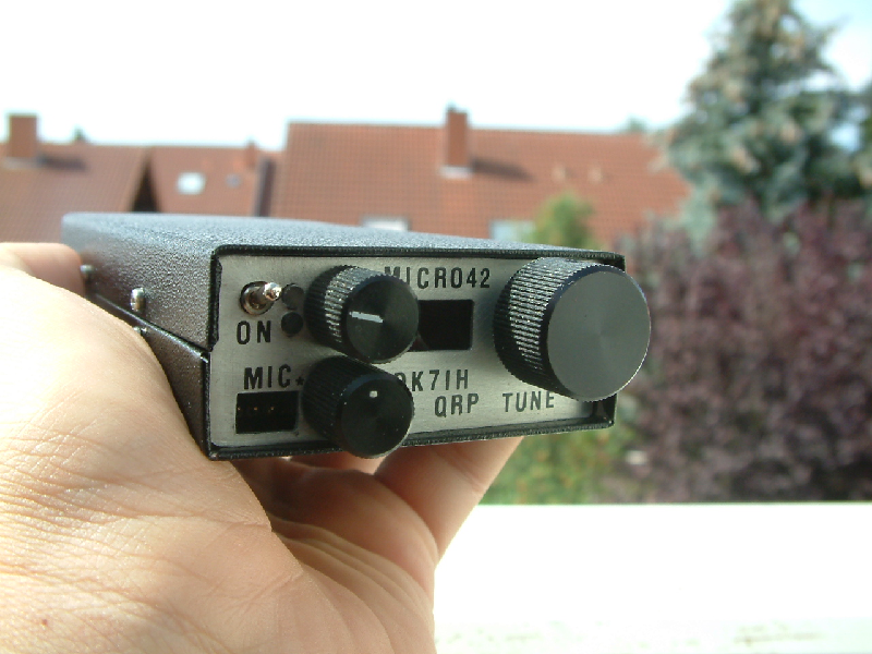
Besides, this transceiver to be discussed here is some sort of a “remake” of a 20 meter rig I built 3 years before. And this time, the transceiver really fits into a shirt pocket without having to wear “XXXXL”- clothing. ;-):
General circuit description (instead of presenting a block diagram)
The rig uses two mixers NE602 plus one filter as central elements. The signal way is reversed when switching from receive to trasmit mode. This is done by 2 relays and is a well known technique for simple QRP rigs. You will find lots of equivalent ideas on the internet (Example 1, Example 2).
But not to ignore the shortcomings of these designs: They are somehow inferior to my requirements, particularly concercing receiver performance. I prefer to have higher signal gain and an AGC circuit. AGC for me is a must. But these designs can be expanded easily, so I added an AGC controlled interfrequency amplifier with dual gate MOSFET BF998 into the receiver’s signal path enhancing performance significantly.
Frequency layout
The frequency generation of the superhet transceiver scheme is simple: Again I use one interfrequency (i. e. 9MHz). The VFO is DDS based on AD9835 operating below the desired radio frequency, which means that it is set to the range of about 2 MHz. Due to this low frequency you could replace the DDS by a VFO if you don’t like the relatively complex work with the software programming and microcontroller stuff). A 2MHz VFO can also be made very stable, so this is an alternative not to be ignoered.
Due to the fact that the schematic is not very difficult to analyze you are kindly requested to refer to it for further talking:
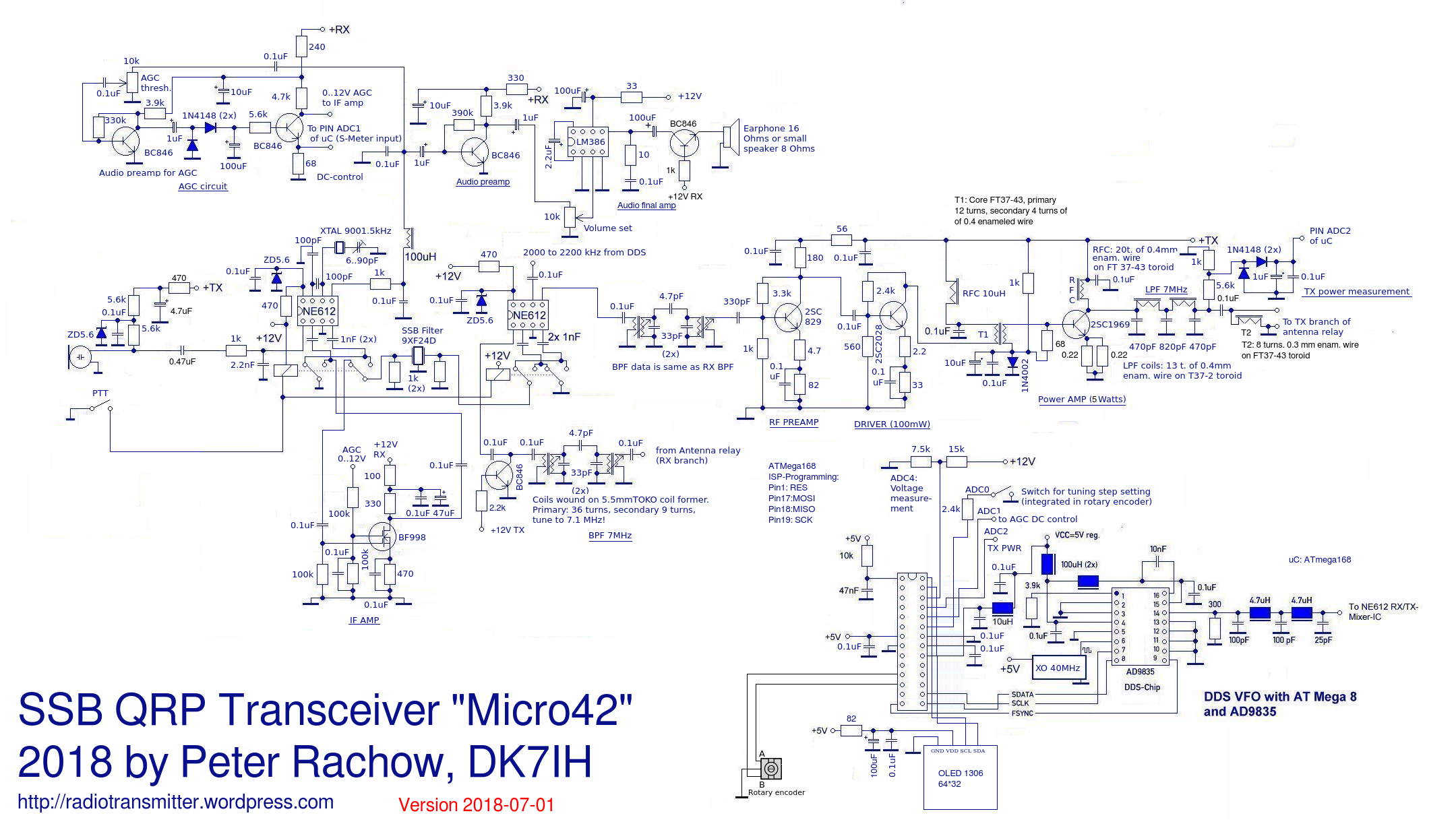
Circuit description
In the center of the schematic you can see the main elements of the circuit: One SSB filter (9MHz), correctly terminated by 2 resistors of 1k each (to ensure proper filter response curve) and two relays with a double set of switches. These relays reverse the way the signal travels through the filter. The advantage of this: You can use the integrated oscillator of the NE612 controlled by a crystal and a tuning capacitor to set the carrier frequency correctly for the lower sideband because the mixer is used as SSB generator and as product detector in common.
A word on chosing the proper relays: An intense examination of the relays’ data sheet is essential. I built a prototype of this transceiver on a breadboard prior to soldering the components to a veroboard. I found that some SMD relays have signifikant coupling capacities between the unused relay contacts (in the range of some Picofarads). So stray coupling was a severe problem. Later I used some second-hand Teledyne RF relays that I had purchased via ebay two years ago (price originally 50€!) for 1€ each. These relays are absolutely superb!
The receiver
Before we go: In the circuit scheme above I missed out the antenna switch relay because I think every homebrewer knows what to do in this case. 😉 So the receiver’s signal path starts with a band filter for 7MHz consisting of to tuned LC circuits. The coupling is relatively loose. As coils I use the well known coil formers in TOKO style with 5.5mm outside measure.
Coil data for the 7MHz band pass filter (BPF) is 39 turns primary and 9 turns secondary of 0.1 mm enameled wire. The respective capacitor is 33pF. This is a high L to C ratio which gives you excellent LC quality factor. This is mandatory especially when working on the 40 meter band, because of the strong broadcasters starting from 7.200 kHz intermodulation might be a problem when the receiver is connected to a high gain antenna and broadcasters’ signals might overload the first mixer (remember that NE612 has a relatively low IM3!). If you still should have problems coping with too strong out-of-band signals you can reduce the coupler from 4.7pF down to 2.7pF.
In practical terms I could not detect any unwanted signal products even when using an antenna with high rf output voltage. One reasons for this is, that there is no rf preamplifier for the receiver. This avoids overloading the first mixer generally.
The NE612 has two mixer inputs and two outputs. This makes it very suitable for this sort of radio. In receive mode pin 2 of the right NE612 is used as signal input. VFO signal is fed into pin 6. The resulting mixer products are taken out from pin 4. Next the 9MHz filter follows from right to left.
The 9MHz IF signal then is fed into an IF amplifier. This one is equipped with a dual gate MOSFET (BF998), gain is about 15dB when full AGC voltage is applied wich leads to about 6V by the 1:1 volatge divider in the applied to gate 2 of the MOSFET.
The left NE612 is the product detector. I use the internal oscillator with a 9MHz crsytal and a tuning capacitor here. This saves building an extra oscillator and simplifies the rig again.
One AF low pass filter made of 1k resistor, 100uF rf choke and a 0.1 uF capacitor eliminates high frequency remainders generated by the mixing process.
The audio stages are also made simple: One preamplifier (using bipolar transistor in grounded emmitter circuit) and a final stage with LM386 transform the signal to a level that is sufficient to be fed into a small 8 ohm loudspeaker or a set of standrd MP3-player headphones. Because the rig is very small and there was definetely no space for a loudspeaker I use headphones instead.
Keep an eye on the power supply switching of the two audio stages. The problem was to eliminate the switching click and pops to a minimum and to avoid acoustic feedback when unsing a loudspeaker. So the audio preamp is only connected to DC on receive. When switching to transmit the charged capacitors avoid instant cut off supplying some Milliseconds DC to the amp until significantly discharged. The main amplfier on the other hand is connected to permanent DC supply. So it won’t pop when switching from tx to rx an vice versa but can cause feedback. To avoid feedback a transistor is used to cut the speaker/earphone from the power amplifier.
AGC
AGC is audio derived. A two stage amplifier provides a DC voltage analog to the audio input sginal strength. First amplifier stage is a common emitter bipolar transistor supplying sufficient audio voltage. This voltage is rectified by a two diode circuit letting only the positive halfways pass. You can use silicon diodes (1N1418) oder Schottky diodes here. An electrolytic capacitor (100uF/6V) provides the time constant respectively DC decay once the signal has disappeared. Output of the DC stage is split. The collector is connected to 12V via a 4.7k resistors causing a voltage drop when the transitor’s conductivity increases. The emitter is fed to the ADC of the microcontroller (pin ADC1) causing a proportional voltage to the voltage of the applied audio signal so that on the OLED an S-meter can be displayed.
The transmitter
An electret microphone picks the operator’s voice. The signal output level of these microphones is high enough to drive the left NE612 (which serves as balanced modulator in this case) directly. Signal input for the mixer should be 200mV RMS according to data sheet. An electret produces about 0.5 to 1 V pp if spoken with a decent voice in the distance of some centimeters. So you have more than enough audio signal power for the modulator.
BTW: Carrier suppression of the modulator is excellent. I achieved 56dB without doing anything else!
The resulting DSB signal then is fed into the SSB filter, the SSB signal subsequently is directly sent into the right NE612. A band pass filter for 7 MHz eliminates the unwanted mixer products. You should have 400 to 500 mV pp of rf signal here when the transmitter input is fully driven. I recommend a two-tone test generator to check out the linearity of this and the remaining amplifier stages!
Next parts of the transmitter are a band pass filter (same coils and capacitors like th rx bandpass filter), a preamplifier and a driver. The later should put out about 150 mW into a 50 ohm load. They are made more linear by emitter degeneration (4.7 and 2.2 ohm resistors for predriver and driver) and negative feedback. This helps to ensure that transmitter performance is fine when IMD3 products are concerned even if the main IMD3 problems usually occur in the final stage.
To transfer the rf power into the final stage proper impedance matching is mandatory. Input impedance of the final stage is fairly low (<10ohms), therefore a broadband (down)transformer is used. Data is: Core T37-43, primary 12 turns, secondary 4 turns of 0.4 mm enamled wire.
Last stage is a single ended linear amplifier in AB mode equipped with a 2SC1969 rf power transistor by eleflow.com.
BIAS circuit: The combination of the 1k resistor, a silicon diode (1N4002 or equ.) and a capacitor sets up the correct bias. Bias is fed into the cold end of the input transformer. Quiescant current should be around 40mA. A good thermal contact between the diode and the transistor is recommended. As the transistor gets warmer the diode will increase its conductivity so reducing bias current. This will prevent thermal runaway effectively!
To avoid bulky output transformers the PI-filter (7MHz LPF) is part of the tank circuit of the final amplifier transistor. For this power level this is an acceptable and practical solution because the output impedance of the stage is nearly equivalent to 50 Ohms. A certain mismatch is not a severe problem. DC to the final transistor is applied via an rf choke, for exact data please refer to the schematic!
T2 helps to suppress unwanted signals that I encountered when taking the transmitter from the dummy load test environment to a real antenna. I observed unwanted parasetic oscillation in the range of about 1MHz. T2 has a low reactance for this frequency range thus eliminating the oscillations in a reilable way by short circuiting them towards ground.
Powered with 12.5V DC the transmitter will put out slightly more than 5 watts PEP.
DDS VFO
AD9835 is a simple but well performing 10-bit DDS chip made by Analog Devices (AD). It is controlled via 3 SPI lines transmitting the frequency data. Maximum output frequency is around 16MHz when the chip is clocked with its maximum clock rate of 50 MHz. Oscillator output voltage is some hundred millivolts peak-to-peak, so you can connect the output directly to pin 6 of the NE612 mixer.
Control signals come from an Arduino Pro Mini board. The microcontroller in this module is, if you are an Arduino user, preinstalled with a bootloader program. I overwrote this small portion of code and use the ATMega168, which is the core of the Arduino, in “native” mode. My software is written in C and transferred via “AVR dude” software using the ISP lines MOSI, MISO, SCK and RESET. These lines are not in the schematic, please refor to ATmega168 data sheet. Alternatively you can use, like shown in the schematic, an ATmega168 controller. So you have to de neccessary wiring on your own.
You will find the source code here. I packed it into an Open Document Text File because of problems I encountered when I tried to store the code into this Blogtext. If you need a compiled HEX-file, please feel free to email me!
Display is a very small OLED with 64 by 32 pixels. The OLED is, to my point of view, a little bit noisy. To suppress any rf traveling on VDD line I use an 82 ohm resistor and a set of bypass capacitors of 100uF and 0.1uF capacity closely connected to the OLED VDD pin to GND.
A low pass filter by the output of the DDS ensures spectral purity and avoids clock oscillator feed through. Remember that if you need another output frequency other than 2 MHz you should redesign the low pass filter.
Frequency control
Tuning is done by a rotary encoder connected to PD5 and PD6 of the microcontroller. I use the pull up resistors internal to the microcontroller, so you won’t see any other things than the mere encoder.
Tunings steps are selected by pushing the encoder knob or another suitable push button. This button is connected to ADC0 in the ATMega168 via a 3.9k resistor. The resulting ADC voltage might be problem because of a certain variation in the values of the pull up resistors that form the second resistor of the voltage divider. There is an outcommented section in the code that will show you the exact ADC value that has to be typed into the code so that key recognition works exactly.
The button once pushed will increase the tuning step by a certain amount of Hz. Steps are 10, 50, 100 (standard step), 250, 500, 1000 and 5000 Hz in and endlessly revolving chain. The step will be reset to 100Hz (standard tuning step) by leaving the tuning knob idle for 2 seconds. That’s all with the controls. Very simple, but sufficient.
Practical aspects
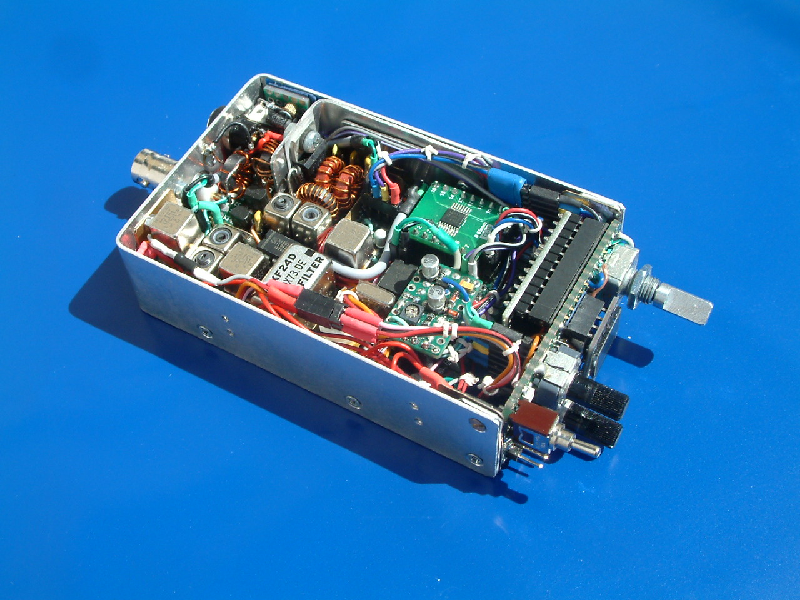
The transceiver is constructed on a double sided veroboard with 6 by 8 centimeters area. Components are through hole and SMD where available. The Arduino is mounted to the front panel (another Veroboard carrying the controls etc.) as well as the OLED is. The veroboard is inserted into an aluminium frame connected to the front panel with 4 lateral M2 screws:
Design hints:
Wiring can be made by using the colored lines stripped from old parallel printer cables. These cables have a diameter of precisely 1mm an fit through the holes of the veroboard excactly.
If you connect any external components that are not on the same veroboard use standard 2.54 mm (0.1″) male and female board connectors! This will make it much easier to dismantle and reassemble the rig in case troubleshooting is neccessary.
Use M2 srews instaed of M3 when building very small rigs like this one!
The reverse side of the main arrangement:
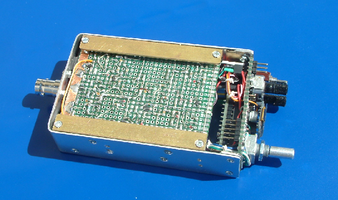
Two brass made bends (from the local hardware store and each cut to a length of 8 centimeters) hold the PCB inside the mounting frame. A winding has been cut into the brass to fix the bends with screws in M2.
Final assembly
Together with 2 halves of a bent aluminium cabinet covered with “DC-fix” (a German manufacturer of self-adhesive PVC coating) the final rig looks like that:
So, that’s the end of the story so far. Now it’s time for going outdoor and test the rig in field use. 😉
73 and thanks for watching!
Peter (DK7IH)
Great pocket trx !
There is some room left for a cellphone speaker (-;
Hello John, yes a celphone speaker might be a solution. But then I would have to operate the trx near my ear and that would look very strange. 😉 73 de Peter
Hy Peter .
There are cell phone speakers for 1 Watt output . My phone has a verry acceptable audio output when the speaker is switched to the ‘loud’ position. A clubmember PE1RLN has used such a small speaker in his QCX with good results. E.g. http://www.china-speakers-manufacturer.com/product/Cellphone-Speaker-UGSP111508-12CW_9452.html
Have fun, John pd7maa
Hi John,
I am currently redesigning the “Cigarette Pack” TRX and have bought the cellphone speakers some time before. They are really great. The sound is much more balanced than with the standard loudspeakers that are available. The only thing that is a little disadvantage is that the audio “pressure” is fairly low. But when mounting the device to a piece of cardboard the sound is amazing.
Thanks for the idea!
Peter
Hi John, thanks for the hint. I have just checked the web but could find not much except from pics on pinterest. Could you just provide a link? 73 de Peter
Hi Peter
Another great design, you next challange is to build a rig into a cigerette packet size case. Have agreat break
John ZL2TCA
Hi John, thanks for the compliment. I had something like that in mind. But because I’m a non smoker I think I have to google the size of a cig pack. ;-))
Edit: Google just told me, that a “Big Pack” should be 6.6 x 8.6 x 2.4 centimeters. That’s a real challenge for a QRP transceiver inside.
73 de Peter
Hello John! You should not have started talking about a “cigarette pack sized” QRP transceiver. 😉
https://radiotransmitter.files.wordpress.com/2018/07/m171_frontboard.png
73 de Peter (DK7IH)
Hi Peter, Well done, you even have enough room for a couple of tactile switches hi. Have been giving it a lot of thought myself and looking at the sandwich approch (RX top, TX bottom) which will double the space provided I use very low profile components. Please keep me updated I am really looking forward to see what you come up with.
Take care and 73
John ZL2TCA
I think i fell inlove in shirt pocket and i think i would try to do this.
9a3xz Mikele
That rig would make a fabulous kit! Right now, I’m recalling a tech guy at the now-defunct Maryland Radio Center in Laurel who built a double-sideband rig for 80 meters into a small box about the size of a cigarette pack back in the late-80’s or early 90’s. I can’t remember his callsign, but his work was mentioned in the QRP Quarterly, as well as elsewhere. There were no surface-mount components in his rig, as I recall, which would make such a rig doable with miniature components like the miniature crystals and other SMD’s.. Congratulations on a fine rig!
Mike, kc8lcy
I think your design of the final tank is wrong. IIRC the formula for the load impedance in VCC*VCC/2*Po
For a 12 volt supply at 5 watts out that would be about 15 ohms, not 50. At 1.5 watts out the match would be close to 50 ohms.
Hi, there seems to be some confusion on the correct formula. I found
“The generalised formula for the output impedance can be given as: ZOUT = VCE/IC.”
(Source: https://www.electronics-tutorials.ws/amplifier/input-impedance-of-an-amplifier.html).
So missed taking the degree of efficiency (abt. 50% in class AB) into account.
73 de Peter.
Fantastic work Peter, I’m so impressed. Your design choices and techniques are similar to some of my projects, although you far exceed the density I have managed to achieve! I attempted a compact ‘walkie talkie’ transceiver for 40 and 20m SSB and CW, over the VK winter. I wanted it for SOTA work.
I based it on the G6LBQ circuit, with mods. Click thru to my site, you’ll see the post and video there. I would be delighted if you posted a comment there. I have subscribed to your channel and blog and will continue my catch-up reading. Keep melting solder. 73 VK3HN.
Thanks, Paul, for your entry. In fact I have discovered your website some time before and I’m also very impressed. I also love to watch your videos, because I’m still struggling with camera and sound hindering me from bringing my projects to YouTube. 😉 Keep on soldering! 😉 73 de Peter
BTW: Actually I didn’t know that you have snow Down Under. Looks a little bit like the situation in Black Forest here close to my front door in winter. Love those mountain and outdoor activities, too! Thanks for the nice video about Fedration Range peak!
Hi Peter, thanks for the quick response. I am very much still learning how to make short, engaging videos, I take about ten times more video than ever makes it to Youtube, altho I am pretty sure that is true for most people.
Your tiny rigs might inspire me to keep working compact! I haven’t yet built a SA621 bilateral design, would like to try that one day. What I like about small rigs is how you need to design both the physical and electronic aspects of the radio together. It’s a true craft.
Federation Range is only 1300m above sea level but is covered with up to a meter of snow at times during winter. The Great Dividing Range stretches from just north-east of Melbourne to Canberra, the summits, 1300 to 2200m, are mostly snow covered from June to September. It makes a nice escape from city life and a great location for SOTA and portable operating, We are lucky in VK3, we have snow till September, then heatwaves by December. 73 VK3HN.
Another question Peter. To test the relays for stray capacitance, did you simply put a digital LC meter cross the open pins? What stray capacitance (pF) would you consider unacceptable?
Hi Paul, I measure with a simple LC meter. And I think, depending on the frequency, some picofards should not be exceeded. 73 de Peter
Hi Peter, I am part way through building your design also, although nowhere near as small. I have the Rx going and its’ not very sensitive although not debugged at present. I was wondering what sort of sensitivity to expect in terms of dBm or uV?
Glenn vk3pe
Hello Glenn, I don’t have any suitable equipment here to measure rx sensitivity exactly. A simple way to estimate the proper function of the recevier I always go is to connect a short peace of wire (abt. 1m length) to the input of the receiver. Then band noise must signifiantly increase and stations must be audible in the speaker with e reasonable S/N-ratio.
From other NE602 designs I know that receiver sensitivity is around 1uV or better.
vy 73 de Peter
Edit: Another test I frequently do is to use an old KYORITSU dip meter. The receiver must be able to detect the signal from a distance of about 10 to 20 meters with the rx connected to my antenna (delta loop). The dip meter only has a coil but no antenna and oscillator output is very low.
OK, Thanks Peter. Currently I am getting about -70dBm but its early days really. I only just tried it yesterday and no time to debug. I’m thinking my injection levels from Si5351 maybe a bit low as i have attenuators in line with them.
One thing though was to alter the low Z winding on the BPF from your 9 to 4 turns. I am using TOKO formers with 31T as the ~15uH to resonate with the 33pF caps. When i tried sweeping the BPF with the 9t, i had an extremely wide response. it covered 40 to 20M bands! Have you altered this in any way. With the 4T i got a nice 40M bp response.
Hello Glenn,
concerning injection levels: I don’t think that is severe. NE602 requires some 100mV pp here so I always found out that signal level tends to be lower than higher because of the need to avoid excessive drive of the LO input of the mixer.
Band pass filter: Maybe when I find time this weekend I will connect a respective bpf to the spectrum analyzer and trace it. Without precise data I only can say that I always had a very sharp peak when tuning it to maximum pass through of desired frequency. But I will try to get exact measurement this weekend then I can say more.
73 de Peter
Edit: OK, now I read your 2nd post, glad to hear that you found the problem causing low amp gain. 🙂
Peter, I found the problem…. The BC846 AF pre-amp was saturated. ie collector at near 0V. Reason was that I had the 1uF Tant coupling cap into the base, reversed. Leakage turned the BC846 fully on.
Sensitivity now is around or better than -100dBm (3uV) from HP8640B sig gen. -110dBm is audible.
I still have the BPF windings as detailed in previous post.
In my version of your project, I have two PCB’s about 100x70mm stacked one over the other. One contains all the RF parts, the other the AGC/AF amp and Tx PA stages. A separate pcb houses the NANO and Si5351 and a 0.96″ OLED.
Thanks for the great project ideas.
glenn vk3pe
Hi Peter,
I was wondering if you could help me. I’m trying to find details of the 9XF24D ssb filter. Do you have a source for the part or the specifications so I can find something similar? I’m learning through constructing (no expert), and a home brew 40m ssb transceiver for SOTA would be a big bonus on longer walks.
Many thanks
73, Ian 2W0IWM
Hello Ian,
unfortunately I have only data for the 9MXF24D filter. This is sold by a German vendor (box73.de) and specified here:
https://www.box73.de/product_info.php?products_id=919
For the 9XF24D filter I only found the outline package which is the same like the 9MXF24D filter. But I am not sure if electrical data is equivalent. But both filters are 2.4kHz bandwidth filters thus I think they might be comparable.
Vy 73 de Peter
Many thanks for your help Peter. A couple of friends and myself are turning it into a small learning project (though i think it’s mostly for my benefit). I will purchase a couple of the 9MXF24D filters from box73.de
The Teledyne 172/12 relays seem to be the expensive part at the moment. I’ve not had your luck with €1 parts on eBay yet hihi.
Excellent blog by the way, I’m enjoying reading through your projects.
73, Ian
Hi,
I’ve reproduced Peter’s Micro40 circuit in recent months, with very good results. Without wishing to devalue Peter’s warning about inferior relays in any way, I used these surface mount relays, commonly available, with excellent results. These ones are good quality, but similar ones are not hard to find.
https://www.altronics.com.au/p/s4130c-2a-12vdc-dpdt-pcb-mount-telecom-relay/
I will post on my build soon, just waiting to get the chance to take it to a SOTA summit for a ‘field test’!
73 Paul VK3HN.
Hi Paul, first congrats for having built the “Micro 42”! 🙂
And thanks for the comment on the relays you have found. I think the crucial word is “Telecom Relay”. Great hint, I am on search for equivalents to the Teledyne ones because they are running out in my stock. Built too many transceivers the recent years. 😉 I have put the relays into socket strips but don’t want to open the “old” rigs to get the relay unplugged for a new project.
vy 73 de Peter
Hi Peter, I must have bought and used 30 of these particular relays in the past few years, in receivers and transceiver projects. When you get onto a good thing, stick to it! Sorry, it’s Micro42 not 40, I knew that. More soon. de VK3HN.
I have recently come across the Skyworks AS169-73 solid state SPDT switches and used them in a multi band BPF for HF. They work extremely well, especially at HF (see data sheets).
They might be a candidate for switching the crystal filter in place of relays perhaps. You would need four of them of course to replicate the relays. They have two select pins which must be fed 180degrees out of phase but easy to do with a tinylogic inverter chip.
Both the AS169 and inverter chip are tiny. Well suited to a tiny HF rig!
I bought the AS169-73 from Farnell/Element14. Around one US$.
glenn
vk3pe
Hi Glenn,
very interesting product, indeed. Should work on a respective breakout board for me. I think I will place an order and test them as a substitute for relay switching RF signals. Thanks a lot and 73 de Peter
Impressive work Peter. One of best pieces of “ham art” I saw. Chapeau bas!
Hi Greg! Thanks very much! 🙂 Vy 73 de Peter