Abstract
A universal VFO with integrated LO for a multi-band transceiver will be presented. The module is based on the well-known Si5351 clock generator. The unit is controlled by an AVR microcontroller (ATMega168 or 328). In addition, the module contains a set of driver stages (consisting of 8 individual switching stages with an open collector circuit) to control up to 8 band relays.
The connections for a rotary encoder are also provided. Likewise the connections for an LCD are accessible by the user. Depending on the software, several different types of LDCs can be used. Software is available for a Nokia5110 black/white LCD and an ST7735 65K color display. In order to be able to control the transmitter optimally depending on the selected band, an MC4725 digital-to-analog converter is built in, which, depending on the band and a predefined setting, can be used to control the gain factor in the transmitter section. A respective circuit is currently under development. Furthermore, the microcontroller measures the operating voltage and displays it on screen as a decimal value.
There are also more analog inputs:
- Keys (6 user keys with different resistors towards GND).
- S-Value (derived from an AGC for example)
- TX Power
A relay for T/R switching also i on baord (not mentioned in the schematic!)
Schematic
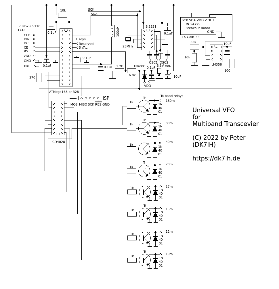
Central part of this VFO is the ATMega168 or 328 Microcontroller. It controls the Si5351 clock chip that provides 4 output sources. They are splitted between 2x OSC0 (as VFO), and 2x OSC1 as LO. Each of the 4 outpus can be set with a seperate capacitor or resistor to control out level and to optimes signal level for the respective mixer stage.
In addition 8 band relays are set depending on the operating frequency. for this purpose 3 output pins in the controllore are fed into a BCD->DEC decoder (CD4028) which is followed by a separate driver stages. Here 8 bipolar transistors have been used because the ULN2003 would require 2 ICs (7 outputs in one and another in the second IC).
In addition an MC4725 DAC has been implemented. It converts a gain value separately stored and set by the user once to control the transmitter gain for each band to ensure the same amount of output for each band used.
Setup
The whole module consists of 2 boards: The main board and the user keys. In addition a rotaray encoder is needed (preferably an optical one) and a Nokia5110 LCD:
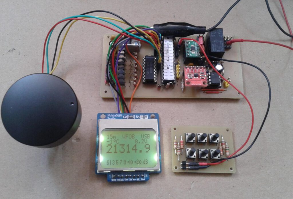
The software is supplied with the module that can be purchased in my QRP shop.