The “Lean Design Transceiver” has been a project to build a simplified but effective 100% analog SSB QRP transceiver with minimum effort. The radio worked fine but there is never anything that can not be improved.
So, this transceiver, originally built in 2018, also has been scheduled for a revision. The problems were minor, mainly on the mechanical side of the design. I have then used a veroboard to connect the front and the rear panel. Later I found this to be inferior under the aspect of ruggedness particularly for a VFO-controlled radio because of problems concerning mechanical stability. Now there is a 2mm aluminum plate carrying the circuit boards which makes the rig much more withstanding to mechanical forces.
Mainly the transmitter section also had to undergo certain changes. The previous version contained a 3-stage amplifier with 4 watts PEP output, I decided to switch to a 4-stage design with about 10 Watts PEP out. To save space for this the new concept the radio has been designed using SMD parts where ever possible.
Last, the basic design using the two NE612 mixers either for receive or transmit mode has been perpetuated. But the switching from RX to TX mode now has been transferred from formerly using two relays for reversing the signal path to one relay changing signals (VFO and LO) at the mixers and simultaneously keeping signal path direction.
The VFO also has been simplified, now it is one oscillator-stage and one buffer amplifier.
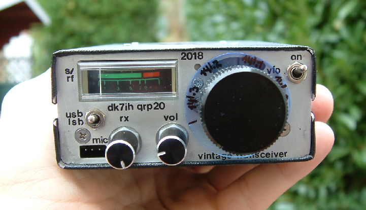
Reused have been front and rear panel, cabinet, Vernierdrive and other non-crucial components.
The circuit (Click for full size!):
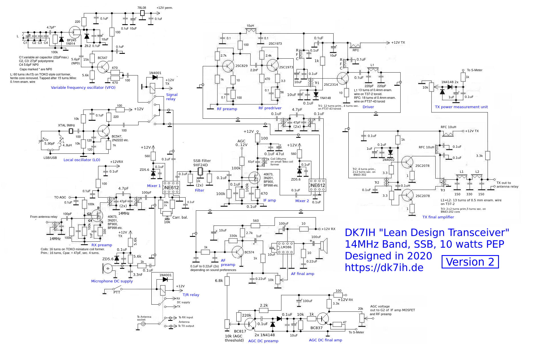
Circuit explanation
Mixer 1, the SSB-Filter, the IF amplifier and mixer 2 make up the core of the radio. Mixer 1 is either receiver mixer or the double sideband generator (DSB), mixer 2 serves as product detector or transmit mixer. Mixer 1 also has been equipped with a circuit for optimizing carrier suppression. With optimized settings of the LO frequency and the 10k pot carrier in best position carrier suppression will be in the range of 45 to 50 dB.
The newly introduced signal relay supplies the VFO and the LO signals to the appropriate mixer depending on wether the radio is currently in receive or transmit operation. In comparison to the previous design this step saved the use of 1 relay.
The IF amplifier has been integrated into the AGC supply voltage chain. When in receive mode the AGC is variable depending on the input signal from the product detector (as well as the rx preamp stage). Rx gain swing in the range of 50 to 60 dB which can cope even with very strong signals. On transmit there it is always on full AGC voltage supplied to the IF amplifier to ensure maximum transmitter output.
On mixer 1 both signals (audio frequency and receive’s radio frequency) are fed into one mixer input (PIN 1 o f the NE612). Signal paths are separated by a low capacity (100pF) that prevents audio frequency flowing into the rf chain and a 1k resistor prevents low Z radio frequency from going into the microphone circuit.
The electret microphone output is high enough, so that (together with the IF amplifier) enough gain is achieved to fully drive the transmitter.
The VFO
Please note that to avoid excess frequency drift some countermeasures have to be taken in the VFO control stage. As indicted in the schematic a combination of polystyrene and NP0 capacitors has been used. The polystyrene capacitors show a reverse temperature behavior in comparison to the coil so that temperature influences are compensated to a certain degree. After 10 minutes of “warm up” the VFO should be settled and only drift some 50 Hz per hour which is suffice for SSB operation.
Receiver
The input stage has been more or less the same like in the predecessor of the radio. A simple prefilter circuit with a low Z end (leading to the 50Ohm-antenna) and a high Z end leading to gate 1 of the dual-gate MOSFET transistor.
After that stage a double circuit filter has been applied providing more selectivity for strong out-of-band-signals. Problems related to unwanted in-band signals causing IMD3-problems have never been encountered even when signals levels where high on the 14MHz-band.
Transmitter
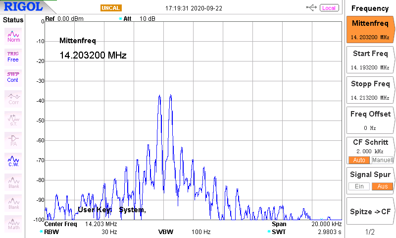
To optimize IMD3-performance and output a 4-stage-design has been used. All transistors are bipolar semiconductors stripped from old CB-radios. The spectrum analyzer screen shows the output with 10 watts PEP applied by a two-tone-signal:
Mechanics
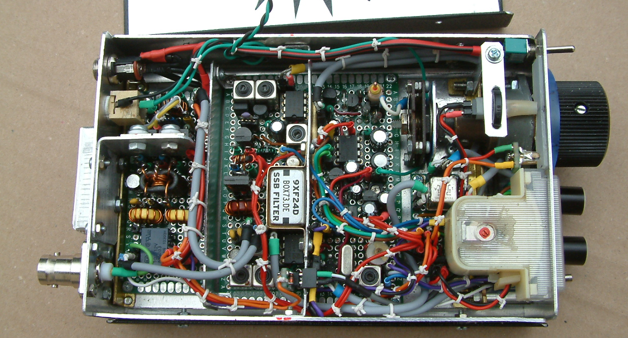
Two veroboards (the 1st 6 by 8 cm and the 2nd 3 by 7 centimeters) carry the whole radio. They are seperated by a sheet metal made of aluminum to avoid stray energy from the power amplifier section into the preamplifier stages.
The larger one of the boards (right part of the picture) holds the mixers, SSB-filter, if amplifier, AGC, the receiver section plus the first 3 stages of the transmitter. The smaller board contains the final radio frequency amplifier and the T/R-relay:
On the air
It is really surprising what can be done with about 8 to 10 watts PEP in an SSB-signal from such a simple radio. Contacts with all over Europe are performed with high reliability when condx are up (as they currently are). A Moscow-based SDR returned the picture of a two-tone-signal transmitted:
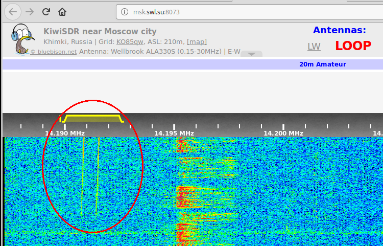
The frequency is slighty drifting upwards due to the fact that warm-up has not been finished yet when the experiment was done.
All in all I have revised another radio optimizing its construction and performance. I think I’m a little bit “Monsieur jamais content” 😉
Vy 73 de Peter (DK7IH)
I think I see 2 problems with the schematic. The IF amplifier is used on both RX and TX, but the AGC voltage on G2 will only be present on receive as the AGC circuit is powered from the +RX line. Perhaps there would still be enough gain on TX anyway?
Also, the microphone amp output is connected via a .1uf capacitor to the same input of the mixer as the output of the RF amp. I suspect that this would load down the RX signal. IIRC, in transceive circuits using the NE612, pin 2 was used for the TX signal (mic) while the RX signal was impressed on pin 1, though pin 1 might have to be grounded via a .1 uf cap on transmit. A 2n7000 could be used for this.
Hi Kenneth,
thanks for reviewing the schematic. Just to answer your statements:
1. Yes, the IF amp still has got enough gain to ensure proper drive of the transmitter when used in TX mode with low AGC voltage. There are layouts that use the same configuration without an intermediate amplifier just connecting the 2 mixers via the SSB filter. But with that specific configuration I found an extra mic amp is better to get more gain. With a low-gain IF amp, as in this design, the drive is very much suffice to get 10 watts pep out of the transmitter with excellent linearity.
2. The decisive element here is the 1k resistor in the audio output of the mic line. It prevents the RF voltage from being dropped very much which would take place because of the output load of the mic circuit. The RF out is low Z and therefore not very much effected by the mic circuit because of the 1k resistor. On the other hand the audio signal does not pass the 100pF cap sited at the end of the band pass filter. It is a simple but effective way to get acceptable signal separation.
BTW: Welcome to my new website here! 😉
73 de Peter
Hi Peter!
Great to see a revision of this classic design of yours. One question though: Can you recommend a certain source for a fitting variable capacitor? Sometimes they are hard to find…
Alternatively I’m playing with the idea of using a varactor instead, so a potentiometer would suffice as main tuning element. Would be great to hear your opinion on this as well.
Many thanks in advance.
Vy 73, Sebastian DJ4PK
Hi Sebastian,
unfortunately I haven’t got a reliable source for these variable capacitors. Currently some are listed within ebay (https://www.ebay.de/itm/Drehkondensator-200pF-Trolitul/333772620142?hash=item4db666016e:g:Gv8AAOSwuLdfk~Ym). This type I use to dismantle, remove the plastic foils and rebuild it as an air capacitor.
A possible but complex solution would be to build one on your own by using brass sheet metal, plastic carriers and a homemade rotator.
Another problem to get is the vernier drive which is even harder to find. Not the best times for vintage design! 😉
vy 73 de Peter
Peter hello,can you tell me where you buy Toko style coil ?
thanks in advance….73 de 9a3xz Mikele
Hi Mikele, here is the URL for the product:
https://www.pollin.de/p/einstellbare-induktivitaet-3l-fe-349-250512?utm_source=google&utm_medium=fshopping&gclid=CjwKCAiAiML-BRAAEiwAuWVggiVTbsdkGg0LYRXN8MIsNGri5aKmzHKP9N-msF6waSCP8oTl0s2D5BoCOEYQAvD_BwE
vy 73 de Peter (DK7IH)
many thanks dear …..
Hi Peter,
just bought lots of these TOKO-style-coils and trying to figure out on how to get the coil out of its aluminium box without damaging it? I just damaged one with screwdriver and pliers. The coil sits in there very tightly in there.
2nd thing: how you are able to wind these tiny coils is beyond me!:)
There are 32 turns whch is handy for BPFs from 40m and above, so we might use it as primary coil. For anything below 40m I ask my doughters to help out:)
BTW: On behalf of all of us, who are in ham radio, especially those like myself (rather beginner in radio constructing), I would like to thank you for the detailed description of each of your projects. It’s great to see your amazing craftmanship online, similarily to VK3HN, VK3YE, Pete Juliano and few more I follow. Thanks again! 73! Waldi, sq8guo
Hi Waldi,
thanks a lot for your reply and the compliments on my website. Very much appreciated. Now for your questions:
I have constructed a tool to press out the interior section from the filter beaker. It is a piece of hard wood with a 5mm diameter hole in it. Into this hole I have put a small piece of brass tubing:
https://dk7ih.de/wp-content/uploads/2020/05/ausdrueckvorrichtung.png
You set the filter in upside-down position onto this tool and press the metal can with a small pair of pliers downward. I use a high-quality pair of needle nose pliers that is set exactly onto the can without touching the plastic carrier the interiors, i. e. bottom of the filter coil.
Rewinding the works best when you have a magnifying glass in a holder and use thin enameled wire, best is 0.15mm to 0.2mm . A product that is OK is this one:
https://www.amazon.de/Daytools-Helfende-Hand-Halter-Beleuchtung/dp/B07KFN48M6diameter.
Good luck and patience is always a good help! 🙂
Vy 73 de Peter
great stuff, thanks a lot, Peter!
very helpful – I’ll try to get such a brass tube or even some sort of thin pen might be of temporary use:)
take care, dear OM!
W>
Hi, Peter!
I noticed you used the NE612 instead of the AN612, but changed it on another radio design. Would it be a good idea to do the same for this radio also, can it be done, or is there a reason you didn’t choose that route?
73,
Franz KM6MQR
Hi Franz, yes you can change the NE612 by AN612. But only if you don’t intend using the internal oscillator inside the NE612. AN612 has got NO internal oscillator. Both designs are completely different and I have never used AN612 as RX mixer. But as DSB generator or TX mixer you can use any of them.
73 de Peter
I am really thankful to the holder of this web site who has shared this great paragraph
at here.
Do you have any video of that? I’d care to find out more details.
Also visit my webpage; *deleted*
For sure, I have:
https://www.youtube.com/watch?v=vPPOCkyHogc
73 de Peter
Do you have a spam problem on this website; I also am a blogger, and
I was wondering your situation; we have devwloped some nice methods and we are looking to swap techniques with other folks, why not shoot me an email if interested.
Feel free to surf to my homepage Kina
Yes I have. Particularly with stupid people who try to post useless URLs into this comment section. But I know what to do.